Substrate, electronic device, and electronic apparatus
a technology of electronic devices and substrates, applied in the direction of printed circuit non-printed electric components, instruments, and details of semiconductor/solid-state devices, can solve the problems of cracking beginning at the place of the bonding material (solder) and achieve the effect of high reliability
- Summary
- Abstract
- Description
- Claims
- Application Information
AI Technical Summary
Benefits of technology
Problems solved by technology
Method used
Image
Examples
first embodiment
[0049]First, a first embodiment of an electronic device (electronic device according to the invention) incorporating therein a substrate according to the invention will be described.
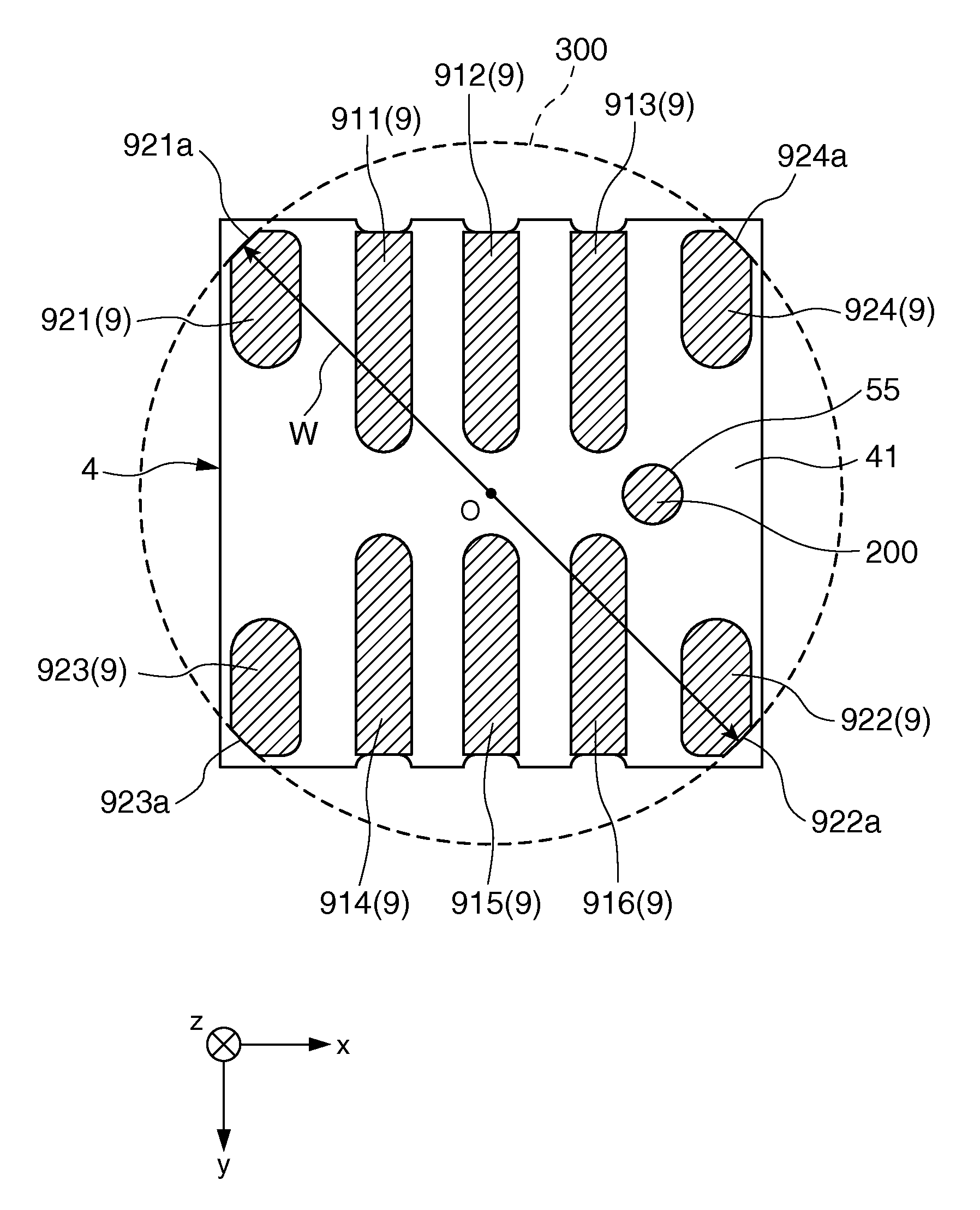
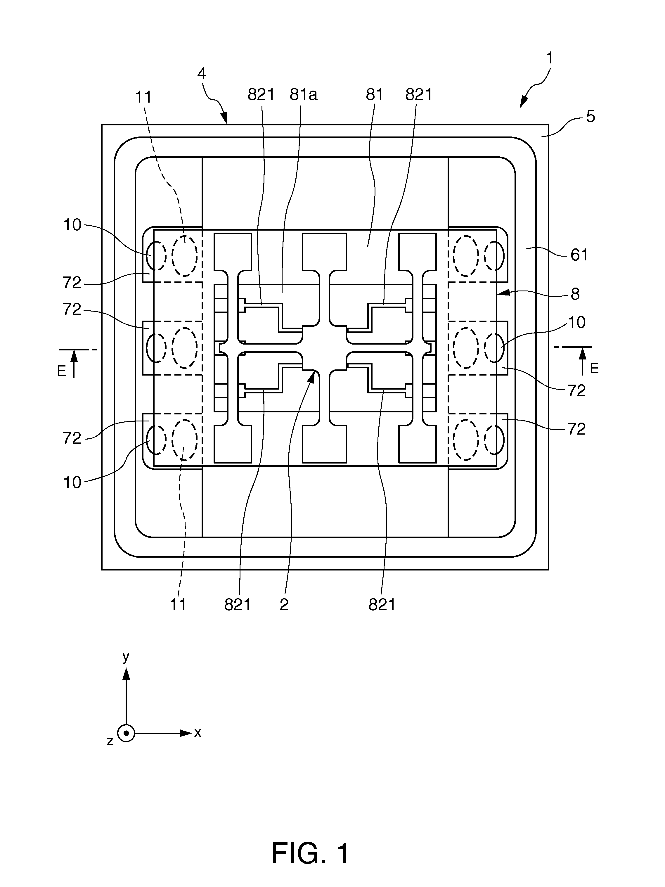
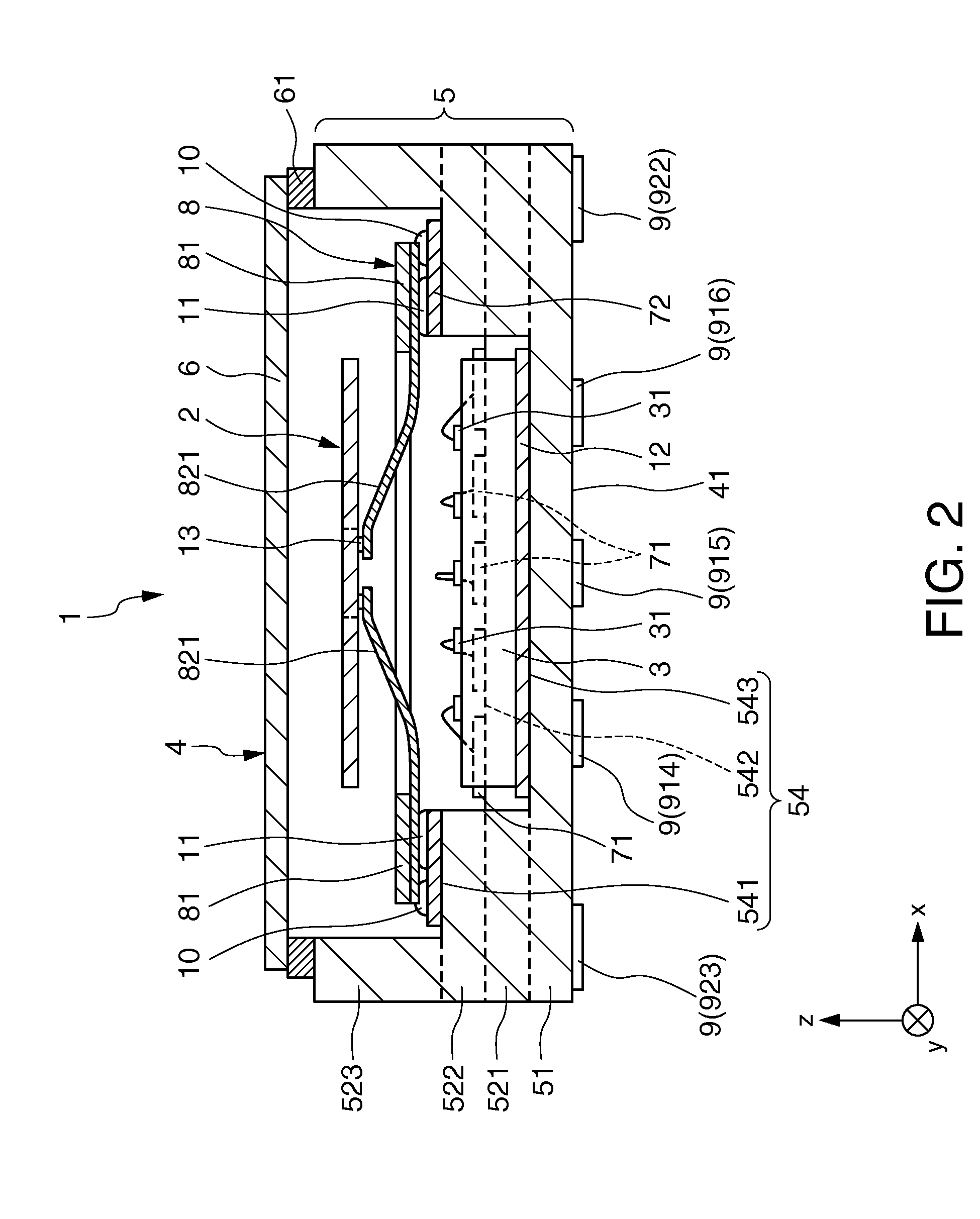
[0050]FIG. 1 is a plan view (top view) showing the first embodiment of the electronic device according to the invention. FIG. 2 is a cross-sectional view taken along line E-E of the electronic device shown in FIG. 1. FIGS. 3A and 3B are plan views of a gyro element of the electronic device shown in FIG. 1. FIGS. 4A and 4B are plan views explaining the driving of the gyro element shown in FIGS. 3A and 3B. FIG. 5 is a plan view showing a supporting substrate of the electronic device shown in FIG. 1. FIG. 6 is a plan view (bottom view) of the electronic device shown in FIG. 1. FIG. 7 is a cross-sectional view showing a state where the electronic device shown in FIG. 1 is mounted on a mounting board. In the following, the front side of the sheet in FIG. 1 is referred to as “upper”, the back side of the sheet...
second embodiment
[0106]Next, a second embodiment of an electronic device of the invention will be described.
[0107]FIG. 8 is a perspective view of the electronic device according to the second embodiment of the invention. FIG. 9 is a cross-sectional view of the electronic device shown in FIG. 8.
[0108]Hereinafter, the electronic device of the second embodiment will be described mainly on the difference from the above-described embodiment. Descriptions of matters similar to those of the above-described embodiment are omitted.
[0109]The electronic device according to the second embodiment of the invention is similar to that of the above-described first embodiment, excepting that the configuration of the circle contacting portion of the sub-electrode terminal is different. Configurations similar to those of the above-described first embodiment are denoted by the same reference and numeral signs.
[0110]In the embodiment, the configurations of the sub-electrode terminals 921 to 924 are similar to each other....
third embodiment
[0116]Next, a third embodiment of an electronic device of the invention will be described.
[0117]FIG. 10 is a plan view (bottom view) of the electronic device according to the third embodiment of the invention.
[0118]Hereinafter, the electronic device of the third embodiment will be described mainly on the difference from the above-described embodiment. Descriptions of matters similar to those of the above-described embodiment are omitted.
[0119]The electronic device according to the third embodiment of the invention is similar to that of the above-described first embodiment, excepting that the configuration of the sub-electrode terminal is different. Configurations similar to those of the above-described first embodiment are denoted by the same reference and numeral signs.
[0120]As shown in FIG. 10, in the electronic device 1 of the embodiment, the sub-electrode terminals 921 and 923 arranged in the y-axis direction are formed integrally with each other, and the sub-electrode terminals...
PUM
 Abstract
Description
Claims
Application Information
 - R&D
- Intellectual Property
- Life Sciences
- Materials
- Tech Scout
- Unparalleled Data Quality
- Higher Quality Content
- 60% Fewer Hallucinations
Browse by: Latest US Patents, China's latest patents, Technical Efficacy Thesaurus, Application Domain, Technology Topic, Popular Technical Reports.
© 2025 PatSnap. All rights reserved.Legal|Privacy policy|Modern Slavery Act Transparency Statement|Sitemap|About US| Contact US: help@patsnap.com


