Unlock instant, AI-driven research and patent intelligence for your innovation.

Method and device for establishing network communication compatibility of terminals

a terminal and network communication technology, applied in the field of network communication, can solve the problems of difficult deployment, tedious installation or modification of applications in the network environment, and unvarying stratification of layers

Inactive Publication Date: 2014-08-05
GEMPLU
View PDF19 Cites 2 Cited by
  • Summary
  • Abstract
  • Description
  • Claims
  • Application Information

AI Technical Summary

Benefits of technology

The invention proposes a system and method for establishing a communication channel between a client application on a client machine and a service application on a device dependent on a terminal. The system includes a formatting module at the client machine to format the messages of the client application in a form understandable by the service application, and a gateway at the terminal to receive and process the messages. The system can be used with various types of networks and communication devices, and can be adapted for secure and efficient communication. The technical effects of the invention include improved communication between client and service applications, enhanced security, and improved efficiency of communication channels.

Problems solved by technology

Thus, for communication between a client and a remote terminal, the stratification of the layers remains unvarying.
Part of this code can be produced by representative generation techniques, but it still remains that the installation or modification of an application in a network environment is tedious.
The deployment difficulties are then of the nature of management and maintenance.
The more complex and long the code of these links is to produce, the greater are the risks of error, especially if said code is written manually.
Furthermore, on account of the large number of software layers between the client application 10 and the service application 12, the communication can suffer from a significant delay in response time.
Moreover, the connections between each software layer involve interfacing problems which add to the aforementioned delays.
The effect of this is a significant delay in response time, since processing is performed at each link.
Finally, this approach lends itself badly to providing security from one end of the chain to the other.
However, it turns out that it is impossible to produce such a card in the current state of the art.

Method used


Image

  • Method and device for establishing network communication compatibility of terminals
  • Method and device for establishing network communication compatibility of terminals
  • Method and device for establishing network communication compatibility of terminals

Examples


first embodiment

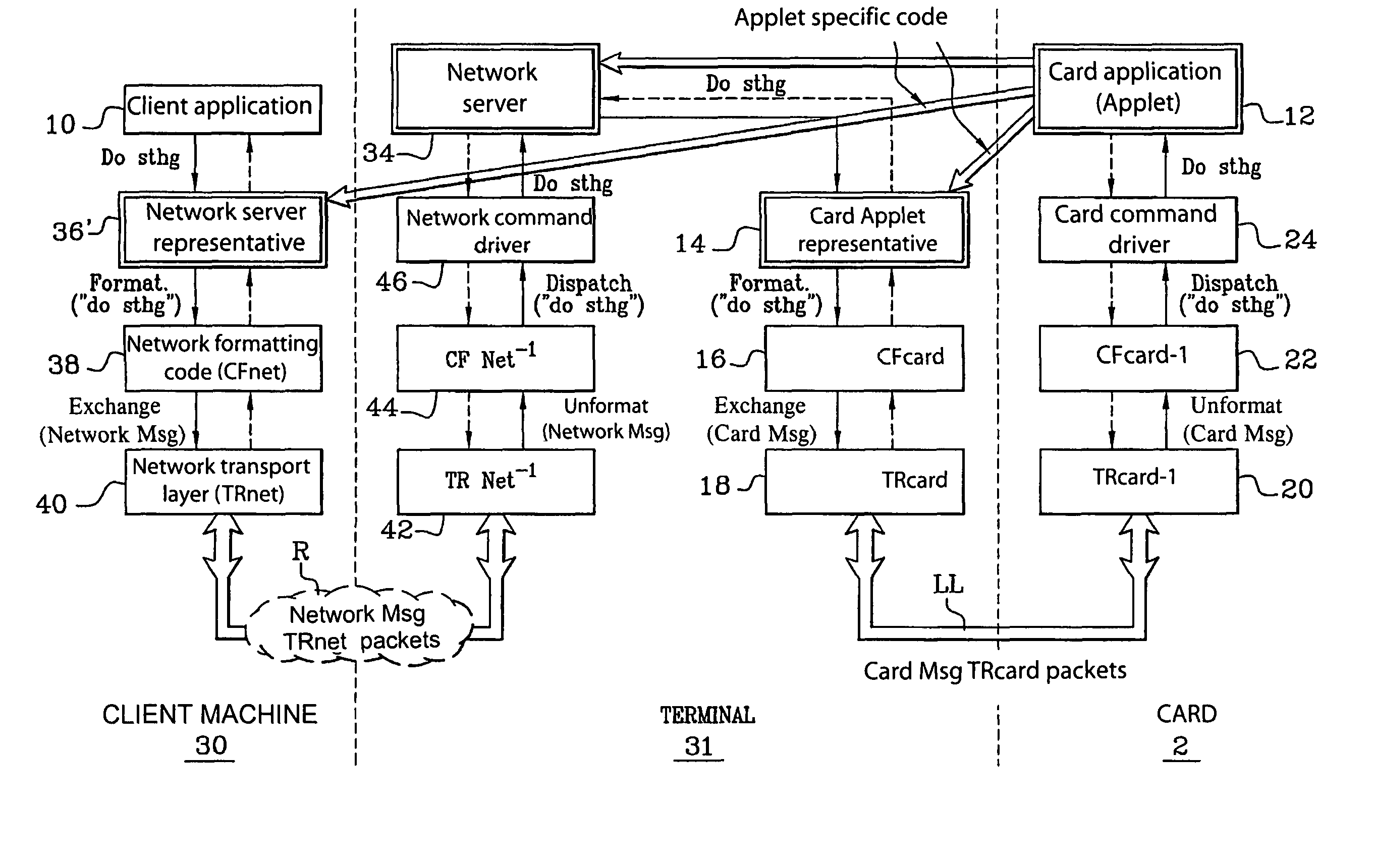
[0088]FIG. 4 depicts the main elements which are involved in the invention.

[0089]In accordance with this embodiment, a message transmission chain is established between a client application 10 situated on a client machine 30 and a card application (Applet) 12 situated in a smart card 2 or any other communicating portable device, associated with a terminal 31. Message transmission between the terminal 31 and the card 2 is provided by a local connection LL. The client machine 30 is remote and communicates with the terminal 31 via a network R, such as the Internet.

[0090]The transmission chain will be described within the context of a message, in this case the command “do Sthg”, sent from the client application 10 to the card application 12.

[0091]At the client machine 30, a “Network Applet” representative 50 is provided for sending appropriate formatting commands from the messages of the client application 10. Thus, in the case of the message “do Sthg”, the “Network Applet” representati...

second embodiment

[0108]FIG. 5 depicts the organisation of the invention, adapted to communication between the client machine 30 and the terminal 31 according to a mode known by the name “socket”. In accordance with the “socket” mode, an exchange format is pre-established between the client and the server, which makes it possible to dispense with the network gateway GTW representative 52 and the layer CFnet 38 at the client machine 31, and the dual layer CFnet−1 44 and the network command driver 46 at the terminal 31. Except for the removal of these elements, the configuration and principle of operation of this embodiment are identical to those of FIG. 4.

third embodiment

[0109]FIG. 6 depicts the organisation of the invention, adapted for the case of a client application 10 situated on the same physical medium as the terminal comprising the gateway GTW 54.

[0110]According to this configuration, the physical medium 60 incorporates a direct internal connection LL′ between the layer CFcard 16′ and the gateway GTW 54. It may be noted that the latter is a gateway of the internal connection / card type. The “exchange” type commands at the output of the layer CFcard 16′ thus dispatched directly to the network / card gateway GTW 54 are retransmitted by the latter to the card application 12 through the successive layers 18 to 24, as in the preceding cases.

[0111]In a variant, the assembly 60 can be connected via the same network / card gateway GTW 54 to both the client application 10 which it incorporates and any other client application connected by network, which imparts versatility at system architecture level.

[0112]Of course, the communication systems of FIGS. 4 ...


PUM


Abstract

In order to set up a communication channel on a link connecting a client application on a client machine and a service application present on a device dependent on a terminal, the client machine includes a representative of the service application. A formatting module is located at the client machine, downstream of the representative, for formatting the client application messages in a form readable by the service application. A gateway is located at the terminal, for receiving the messages readable by the card and transmitting them to the service application. Typically, the communicating device is a smart card, and the service application is a card application. The link is typically a network, for example of the Internet type.

Description

[0001]This disclosure is based upon French Application No. 01 / 10390, filed Aug. 2, 2001, and International Application No. PCT / FR02 / 02455, filed on Jul. 11, 2002, the contents of which are incorporated herein by reference.BACKGROUND OF THE INVENTION[0002]The invention concerns network communication, for example between a server terminal and an application terminal. It relates more particularly to a method and device making it possible to establish a communication channel on a network while the terminals do not have the same software interface for exchanging messages on the network. Such a situation arises, for example, when the server terminal is embodied by a smart card or the like.[0003]In the following description, consideration will be given to the case of communication with a smart card comprising a service application (Applet) written in a high-level language, in particular an object-oriented language, such as Java, C++, etc. The assembly constituted by the card and the servic...

Claims


Application Information

Patent Timeline
IPC IPC(8): G06F15/16G06F15/173G06F15/177H04L29/06
CPCH04L63/0853H04L29/06H04L63/0428H04L69/08H04L9/40
Inventor LAGOSANTO, LAURENTVANDEWALLE, JEAN-JACQUES
Owner GEMPLU