Wad with ignition chamber

a technology of ignition chamber and shot shell, which is applied in the field of shot shells, can solve the problems of performance limitations, the maximum velocity of a given payload is generally restricted, and the performance of conventional shot shell cartridges has reached a performance plateau, etc., and achieves favorable pressure and temperature conditions, accelerate ignition of propellant powder, and increase local pressure

Active Publication Date: 2014-08-12
AMMUNITION OPERATIONS LLC
View PDF121 Cites 15 Cited by
  • Summary
  • Abstract
  • Description
  • Claims
  • Application Information

AI Technical Summary

Benefits of technology

[0007]Upon firing, the primer blast is directed into the ignition chamber so as to contain the majority of the primer blast for an additional time. This generally aids in expediting ignition of the propellant powder by increasing the local pressure within the ignition chamber. The increased pressure generated by the containment of the primer blast within the ignition chamber or tube helps promote favorable pressure and temperature conditions and direct ember / particulate emission into the trapped propellant to enable quicker propellant ignition. The quicker propellant ignition increases the pressure further (in addition to the gas pressure generated by the primer blast) within the ignition chamber and accordingly provides an added thrust to the projectile of the ammunition system. Such added thrust in turn generally provides extra volume for the propellant to burn, effectively lowering the pressure. This further enables use of faster burning, more efficient powders to achieve higher than normal velocities while maintaining normal operating chamber pressures. Higher velocities can enable use of smaller shot sizes whose energy is more comparable to shot made from denser materials to achieve desired effectiveness. The tube or ignition chamber also can be weakened, such as by cuts or prestressing areas of the tube or ignition chamber, in order to help control and facilitate controlled failure of the tube and expedite ignition of the propellant outside the tube.

Problems solved by technology

Conventional shotshell cartridges have, however, reached a performance plateau wherein the maximum velocity for a given payload generally is restricted by the standard operating pressure limits set forth in the Sporting Arms and Ammunition Manufacturers Institute, Inc.
Such performance limitations have been observed in particular with steel loads required for use while hunting waterfowl and other similar game.
Steel loads have an inherent disadvantage in performance properties resulting from the decreased density of the steel material versus similar size lead shot / loads.
This handicap in energy levels for a given pellet size typically requires that a steel load use larger diameter pellets to ensure reasonable energy levels for game harvesting, and in doing so significantly lowers the number or volume of pellets a payload can contain, which in turn limits or hampers the effectiveness of the shotshell in use, particularly for game harvesting.

Method used


Image

  • Wad with ignition chamber
  • Wad with ignition chamber
  • Wad with ignition chamber

Examples


Embodiment Construction

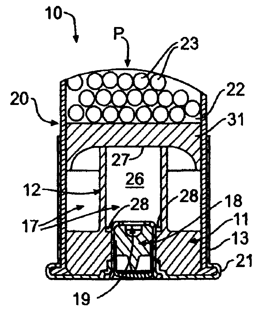
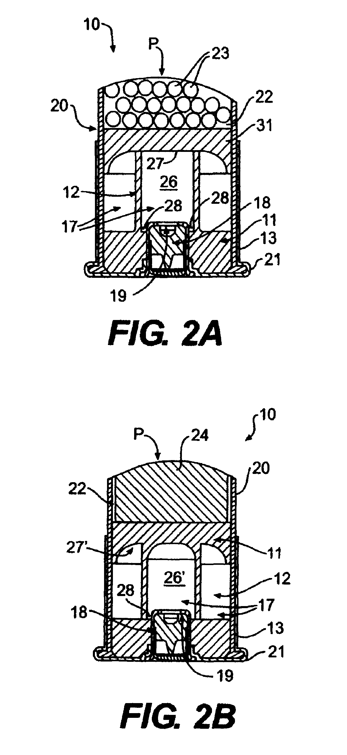
[0019]The present invention is directed to improvements in the performance of ammunition including small arms ammunition such as shotshells, rimfire / centerfire cartridges, and other rounds, as well as for muzzle loading sabots, and other types of ammunition. Accordingly, while the present invention is illustrated herein in various example embodiments including use in shotshells, it will be understood that the wad of the present invention further can be used with a variety of other types and calibers of ammunition. Accordingly, as shown in FIGS. 2A-2B, 3A-3B and 4-5, the present invention generally can include a shotshell or similar round of ammunition 10 having a wad 11 or similar structure having an additional inner tube or ignition chamber 12 located in a rearward portion or section 13 of the shotshell or in a firearm chamber 16 (FIG. 6A) that contains the powder or propellant charge 17, which generally can be both (inside and outside of the ignition chamber or tube) for the round...


PUM


Abstract

A wad or basewad for ammunition includes an ignition chamber. The ignition chamber can be integrally formed with the payload wad, basewad, or battery cup or can be attached to the payload wad, basewad, or battery cup. The ignition chamber communicates with a primer of the ammunition to receive and contain the primer blast for at least an initial period of time. This facilitates faster initial ignition of the propellant of the ammunition, and consequently allows higher performance levels to be achieved. Other advantages regarding other applications of this invention include cleaner burning loads, greater economy, and lower perceived recoil.

Description

CROSS REFERENCE TO RELATED APPLICATIONS[0001]The present Patent Application is a continuation-in-part of U.S. patent application Ser. No. 12 / 606,447, filed Oct. 27, 2009, which is a formalization of previously filed, co-pending U.S. Provisional Patent Application Ser. No. 61 / 108,678, filed Oct. 27, 2008, and U.S. Provisional Patent Application Ser. No. 61 / 113,286, filed Nov. 11, 2008, by the inventors named in the present Application. This Patent Application claims the benefit of the filing date of the United States Patent Application and the Provisional Patent Applications cited above according to the statutes and rules governing provisional patent applications, particularly 35 U.S.C. §119(a)(i) and 37 C.F.R. §1.78(a)(4) and (a)(5). The specification and drawings of the United States Patent Application and the Provisional Patent Applications referenced above are specifically incorporated herein by reference as if set forth in their entireties.FIELD OF THE INVENTION[0002]The present...

Claims


Application Information

Patent Timeline
Patent Type & Authority Patents(United States)
IPC IPC(8): F42B14/06F42B7/08
CPCF42B7/08F42C19/02
Inventor SCHLUCKEBIER, DAVID K.CROSS, KEVIN R.BUCKMASTER, RICKY J.WILDMAN, SPENCER D.
Owner AMMUNITION OPERATIONS LLC
Why Eureka
Try Eureka