
Uniform equipment mounting system

a technology of equipment mounting and uniformity, applied in the direction of supporting structure mounting, electrical apparatus construction details, furniture parts, etc., can solve the problems of limited standardization of equipment and rack dimensions, less standardization of mounting structures, and the width of equipment can vary, so as to enhance the load bearing rating of equipment racks, simplify and increase safety in the workplace

Active Publication Date: 2014-08-12
ZONIT STRUCTURED SOLUTIONS LLC
View PDF17 Cites 11 Cited by
  • Summary
  • Abstract
  • Description
  • Claims
  • Application Information

AI Technical Summary

Benefits of technology

The system enables efficient installation, reconfiguration, and maintenance of equipment by standardizing mounting practices, reducing capital expenditures, and facilitating the reuse of mounting hardware, while improving accessibility and reducing downtime.

Problems solved by technology

There is limited standardization of the dimensions of the equipment and the racks, and even less standardization of the mounting structure for mounting the equipment to the racks.
In addition, the width of the equipment can vary, and the hardware required for mounting is not standardized.
This results in considerable difficulty in installing and accessing the equipment, especially in the case of rack rails because how they attach to the equipment, how far they slide out, how they lock and release, how one removes a piece of equipment from the rack, etc., all vary.
This is frustrating to personnel responsible for the equipment, and it is a significant impediment to reconfiguring the layout of equipment and racks as may be desired.
However, the difficulty of removing and remounting equipment sometimes weights upon such decisions.
In some cases, the problems caused go beyond inconvenience.
This can require down time, which is difficult to schedule, and it is potentially disruptive and expensive.
The lack of standardization of mounting equipment also results in significant capital expenditures.
This can be a significant expenditure, particularly in the case of data centers that utilize a large volume of equipment.
Moreover, as equipment is added and other equipment is removed and replaced, a large volume of such mounting hardware may be accumulated.
Because this mounting hardware is often specially designed for a particular manufacturer and / or a particular piece of equipment, it is difficult to efficiently collect and reuse such mounting hardware.
The result is that data centers often accumulate a large volume of mounting hardware, representing a significant capital expenditure, which the data center operator does not know whether to retain.

Method used


Image

  • Uniform equipment mounting system
  • Uniform equipment mounting system
  • Uniform equipment mounting system

Examples


Embodiment Construction

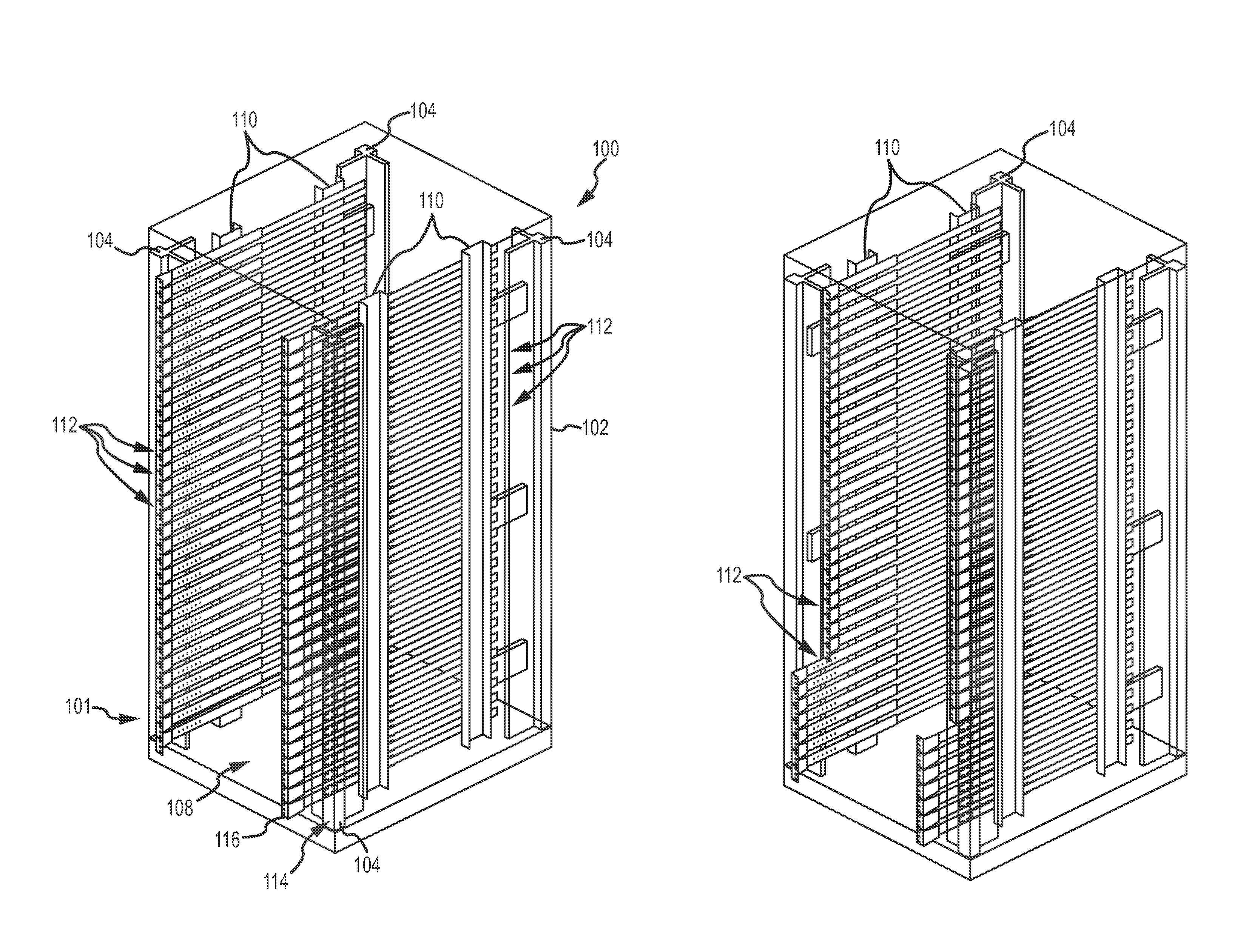
[0048]In the following description, the invention is set forth in the context of a specific rack system configuration for use in a data center or similar environment for mounting EDP equipment. The invention has particular advantages for this environment due to the large volume of equipment, the variety of equipment and the likelihood of periodic reconfiguration of equipment and rack layout in such environments. However, it will be appreciated that various aspects of the invention are more broadly applicable to other equipment mounting environments and in connection with other types of equipment. Accordingly, the following description should be understood as illustrating the invention and not by way of limitation.

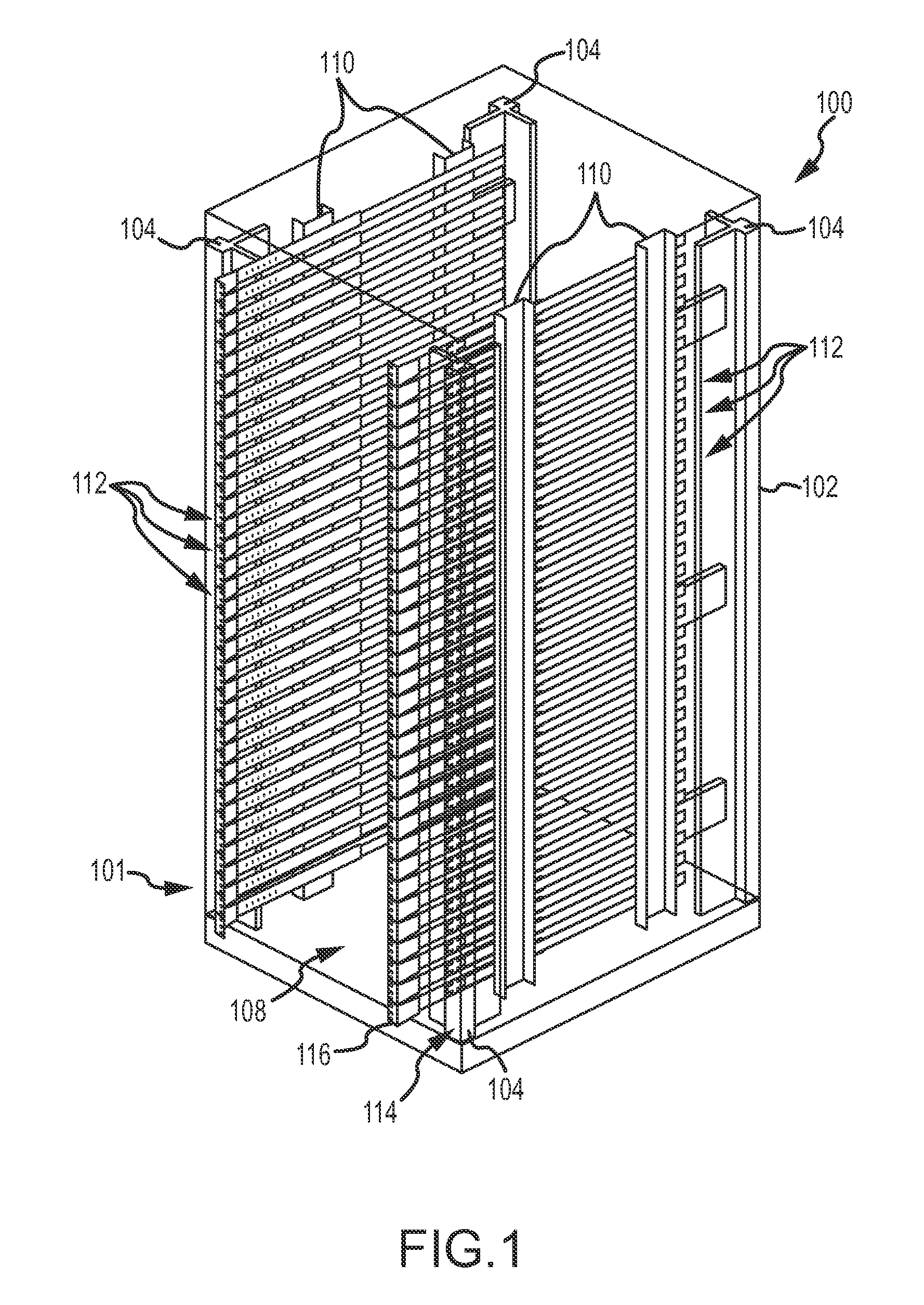
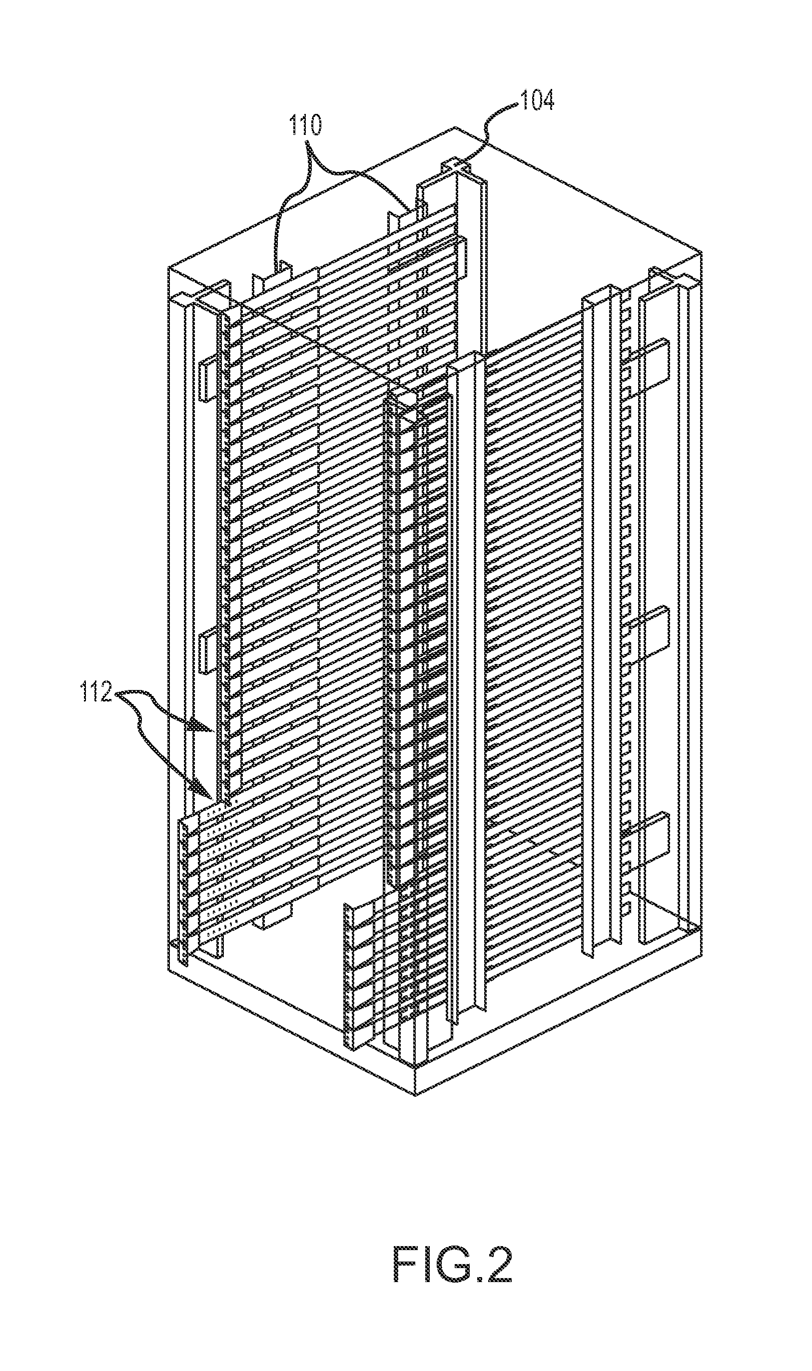
[0049]Referring to FIG. 1, a perspective view of a rack 100 including a uniform mounting system 101 in accordance with the present invention is shown. Additional details of the rack 100 and configurations are shown in FIGS. 2 and 3. It will be appreciated that the present i...


PUM

PropertyMeasurementUnit
depthaaaaaaaaaa
depth axisaaaaaaaaaa
widthsaaaaaaaaaa

Abstract

A universal mounting system is provided for use in connection with substantially any type of electronic equipment so was to reduce or substantially avoid the need for rail kids or other mounting assemblies that are its equipment specific for mounting equipment to racks. In one implementation, a uniform mounting system (101) includes a number of rail and slider assemblies (112). Each of the rail and slider assemblies includes a slider that is slightly mounted on a support rail. Each of the slider is includes mounting flange is and brackets for mounting the slider to a piece of equipment. The mounting flanges 116 that's collectively define a segmented vertical rail. A safety stop mechanism can be used to define very a offset figurations of the equipment with respect to a front end of the rack.

Description

CROSS-REFERENCE TO RELATED APPLICATION[0001]This application is a continuation of Ser. No. 12 / 892,009, entitled, “Uniform Equipment Mounting System,” filed on Sep. 28, 2010, which is a continuation-in-part of International Patent Application No. PCT / US2009 / 038851, entitled, “Uniform Equipment Mounting System,” filed on Mar. 30, 2009, which claims priority from U.S. Provisional Application No. 61 / 040,542, entitled, “Uniform Equipment Mounting System,” filed on Mar. 28, 2008; U.S. Provisional Application No. 61 / 040,924, entitled, “Uniform Equipment Mounting System,” filed on Mar. 31, 2008; U.S. Provisional Application No. 61 / 157,118, entitled, “Uniform Equipment Mounting System External Bearing With Integrated Insertion Guide,” filed on Mar. 3, 2009; and U.S. Provisional Application No. 61 / 157,113, entitled, “Uniform Equipment Mounting System Simplified Mechanism With Safety Stop,” filed on Mar. 3, 2009, the contents of all which are incorporated herein as if set forth in full.FIELD O...

Claims


Application Information

Patent Timeline
Patent Type & Authority Patents(United States)
IPC IPC(8): A47B95/00
CPCH05K7/1489Y10T29/49002A47B88/427A47B88/43A47B2088/4235Y10T29/49826Y10T29/49947Y10T29/49948Y10T29/4995H05K7/183H05K7/186A47B2210/0054A47B2210/0059
Inventor CHAPEL, STEVEPACHOUD, WILLIAM
Owner ZONIT STRUCTURED SOLUTIONS LLC
Learn More