
Power supply system, power cable distributor, power supply subrack and integrated equipment

a power supply system and power cable technology, applied in the direction of electrical apparatus casings/cabinets/drawers, electrical apparatus connections, electrical components not printed, etc., can solve the problems of high cost of pss reproduction, unsuitable mass production, and difficulty for operators to connect power input cables, etc., to achieve low cost, broaden the application range of expensive, and facilitate implementation

Active Publication Date: 2009-03-19
HEWLETT-PACKARD ENTERPRISE DEV LP
View PDF13 Cites 0 Cited by
  • Summary
  • Abstract
  • Description
  • Claims
  • Application Information

AI Technical Summary

Benefits of technology

[0009]Embodiments of the present invention provide a power supply system for equipment, which enables a PSS of fixed dimensions to fit into integrated equipments of different depths so that operators can connect input cables easily and the application range of the PSS of fixed dimensions can be broadened.
[0022]It can be seen from the technical scheme above that the power supply system of the present invention includes a PSS and a PCD connected to the PSS, wherein the PCD introduces electrical signals from power input cables via the first connector and transmits the electrical signals to the second connector which in turn output the electrical signals to the power module(s) of the PSS. It can be seen from the internal structure of the PCD that the present invention is easy to implement and requires low cost. PCDs of various dimensions can easily be manufactured to match the PSS of fixed dimensions in practical applications. Furthermore, when the depth of the PSS differs greatly from that of the integrated equipment, the expensive PSS need not be replaced, a PCD of appropriate depth (dimensions) can be connected to the PSS to make the total depth of the PSS plus the PCD match the depth of the integrated equipment, hence it will not be difficult to connect the power input cables. By adopting low-cost PCDs, the technical scheme of the present invention broadens the application range of the expensive, fixed-dimensioned PSS and enables the PSS to match integrated equipments of different depths.
[0023]Furthermore, compared with the conventional art in which every power module needs an individual group of power input cables, the present invention requires much less power input cables since every group of the electrical signals introduced from the power input cables via the PCD can be fed to a plurality of power modules in the PSS. This is of special significance to high power equipment since the technical scheme of the present invention keeps cables in order on the surface of the equipment so that the equipment will not need any excessive space.
[0024]In addition, the PCD may also include switches to turn on / off the electrical signals introduced via the PCD and an electrical signal may be fed to a number of power modules, therefore a switch can control the power supply of a number of power modules and an operator can easily turn off all switches to power off all power modules, hence the problem of overload and system malfunction, which are caused by powering off power modules asynchronously, can be prevented to a certain extent.
[0025]Moreover, the power supply system of the present invention can be adapted to different environments by simply transforming voltages in the PCD. For example, the power modules of many high power PSSs in the conventional art are unable to provide consistent power output when the public power supply is 220 Vac in some areas and 110 Vac in others, new PSSs with more power modules have to replace the original ones in order to provide integrated equipments with required power in the existing power supply system. Such practice requires considerable cost. According to the technical scheme of the present invention, the voltage of the power input can be transformed simply in the low-cost PCD, e.g., from 110 Vac to 190 Vac, before the power is fed to the PSS, hence the power output by the PSS power modules to the integrated equipment will basically meet the requirements of the integrated equipment without replacing the original PSS.

Problems solved by technology

As a number of power input cables are to be connected to the rear end of the PSS, it will be difficult for operators to connect the power input cables since the power input sockets of the PSS are far away from the surface of the rear end of the integrated equipment and the PSS is usually of low height.
However, such practice is unsuitable for mass production and the cost of such PSS reproduction is high.
For example, the power modules of many high power PSSs in the conventional art are unable to provide consistent power output when the public power supply is 220 Vac in some areas and 110 Vac in others, new PSSs with more power modules have to replace the original ones in order to provide integrated equipments with required power in the existing power supply system.
Such practice requires considerable cost.

Method used


Image

  • Power supply system, power cable distributor, power supply subrack and integrated equipment
  • Power supply system, power cable distributor, power supply subrack and integrated equipment
  • Power supply system, power cable distributor, power supply subrack and integrated equipment

Examples


first embodiment

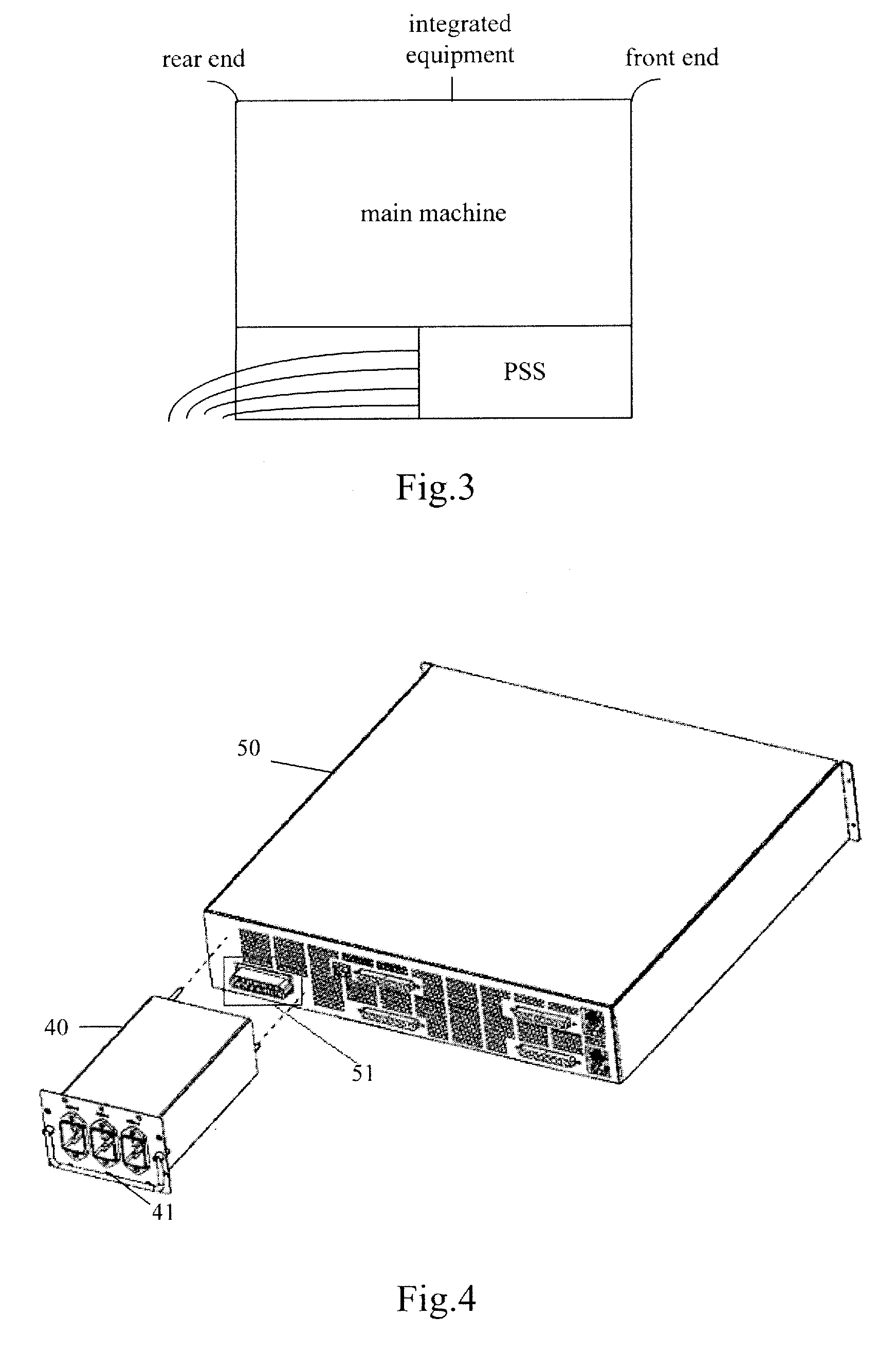
[0041]FIG. 4 is a schematic of the physical structure of the power supply system in the present invention. As shown in FIG. 4, the AC power supply system in accordance with the embodiment includes PSS 50 and PCD 40 connected to the PSS 50.

[0042]Concerning the external structure of the PCD 40, the PCD 40 includes a socket-type first connector 41, and also includes at the rear end a second connector (not shown in the drawing). The PSS 50 includes a third connector 51, and the second connector is adaptive to the third connector 51. In practical applications, the second connector at the rear end of the PCD 40 is socket jointed to the third connector 51 to physically and electrically connect the PCD 40 and the PSS 50. It should be noted that the coupling means between the second connector and the third connector 51, which electrically connect the PCD 40 and the PSS 50, is not limited to socket joint and clamping connection, it may also be other types of coupling means such as cable conne...

second embodiment

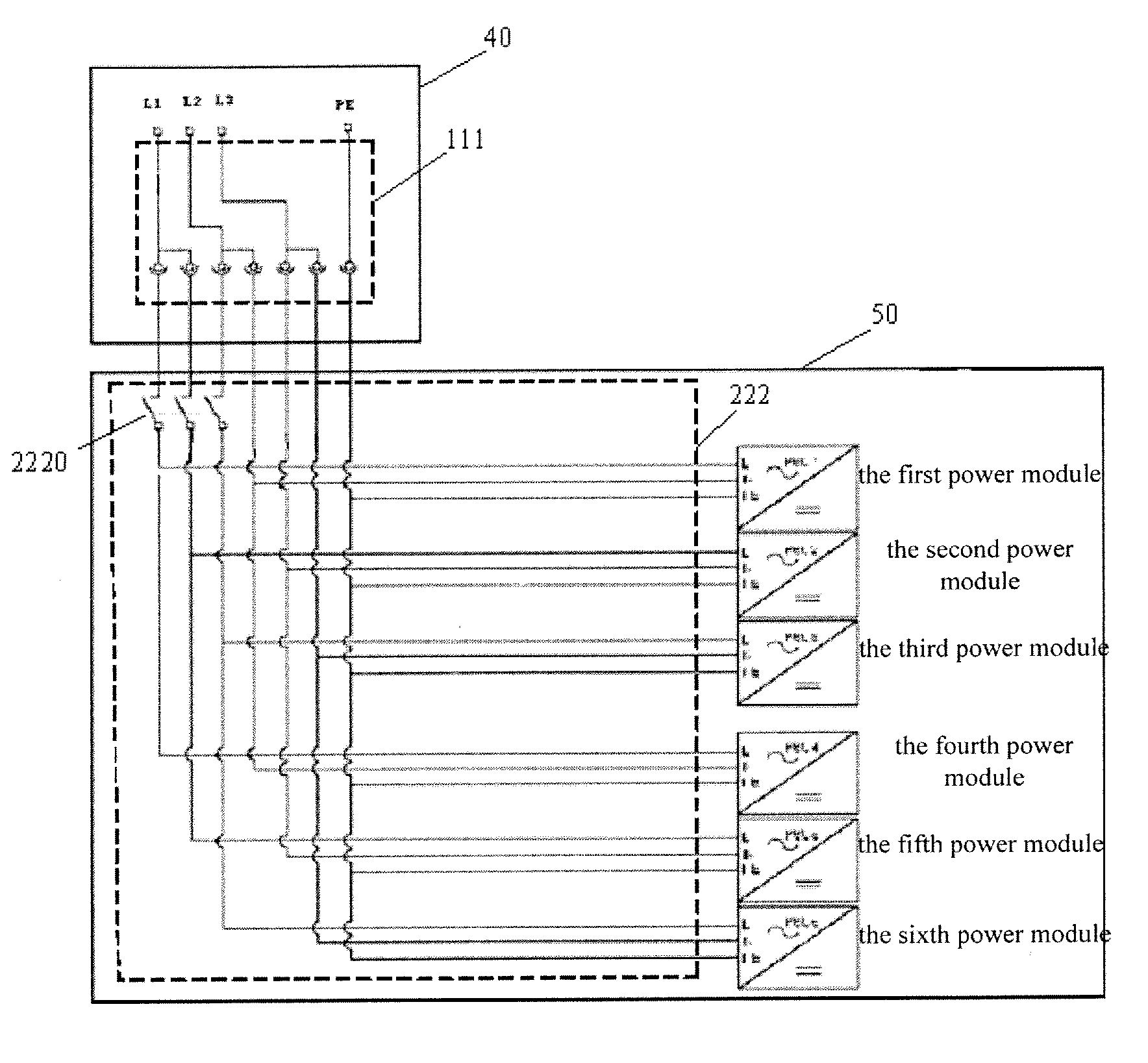
[0045]FIG. 10 is a schematic of the physical structure of the power supply system in the present invention. The PCD 40 in this embodiment is an AC PCD. The external structure of the PCD 40 shown in FIG. 10 indicates that the PCD 40 includes the first connector 41, the PSS 50 includes the third connector 51, and the PCD 40 also includes at the rear end a second connector (not shown in the drawing) adaptive to the third connector 51. It can be seen by comparing FIG. 10 and FIG. 4 that this PCD differs from that in FIG. 4 in the structures of the first connector 41 and the third connector 51 in order to match the corresponding power input cables. The first connector 41 in FIG. 10 includes a plurality of input terminals to match the output terminals of the power input cables, and the first connector 41 introduces multiple groups of electrical signals from the power input cables. The input terminals are classified into “input positive”, “input negative” and “grounding protection”. Each o...


PUM


Abstract

A power supply system is provided, which includes a power supply subrack (PSS) and a power cable distributor (PCD). The PSS includes one or more power modules and a third connector (51), and the PCD is adapted to introduce one or more electrical signals from power input cables. The third connector (51) in the PSS is connected to the PCD and adapted to feed the introduced electrical signals to the power modules. Furthermore, a power cable distributor, a power supply subrack adapted to work with the PCD and an integrated equipment are provided.

Description

[0001]The present application claims the priority of Chinese patent application No. 200610161040.X filed at the State Intellectual Property Office of China on Dec. 4, 2006 entitled “power supply system, adapter and application apparatus”, the contents of which are incorporated in its entirety herein by reference.FIELD OF THE INVENTION[0002]The present invention relates to technologies of power supply for equipment, and particularly, to a power supply system, a power cable distributor, a power supply subrack and an integrated equipment.BACKGROUND OF THE INVENTION[0003]In the communication industry, the following two modes, one is alternating current input 220 Vac (110 Vac) and the other is direct current input −48 Vdc (−60 Vdc), are usually adopted as power supply for high power equipments. Normally, an integrated equipment requires the width of an embedded power supply subrack (PSS) to be 19 inches or 23 inches so that the PSS can be embedded conveniently into a standard integrated ...

Claims


Application Information

Patent Timeline
Patent Type & Authority Applications(United States)
IPC IPC(8): H02J3/00H01R13/66
CPCH05K7/1457
Inventor HE, YINGYANG, PINGWANG, ZHIYONGZHOU, WENXIANGLI, BAOHONG
Owner HEWLETT-PACKARD ENTERPRISE DEV LP
Learn More