Medication administering device

a technology for administering devices and medications, applied in the direction of intravenous devices, other medical devices, infusion needles, etc., can solve the problem that the product is harder for patients to use, and achieve the effect of easy removal of the needle cap or protective cap

Active Publication Date: 2014-08-12
PHC HLDG CORP
View PDF47 Cites 59 Cited by
  • Summary
  • Abstract
  • Description
  • Claims
  • Application Information

AI Technical Summary

Benefits of technology

[0008]It is an object of the present invention to solve the above-mentioned problems and provide a medication administering device with which the preparation syringe can be attached and detached simply and reliably, and both reliability and ease of use can be improved.
[0011]Consequently, after the preparation syringe has been mounted to the syringe cover, the syringe cover can be inserted along the inner peripheral face of the piston case until it is in close proximity to the piston. This stabilizes the mounting of the syringe cover to the piston case, and prevents the occurrence of problems such as the preparation syringe falling out of the syringe cover, so the syringe cover can be placed more securely inside the device.
[0013]As a result of this constitution, the user can easily mount the preparation syringe to this medication administering device, and there is no need for alignment of the piston and the preparation syringe. Therefore, the user has to do less work.
[0015]With this constitution, a medication administering device can be provided with which the syringe cover is easy to mount and more difficult to remove, that is, easy to mount and resistant to coming loose, so ease of use and reliability are excellent.
[0017]With this constitution, the distal end cap moves in conjunction with the syringe cover when the distal end cap is attached to the main body, so even if the syringe cover is not properly attached, the syringe cover can still be guided to the proper mounting position. As a result, the user can easily and reliably mount the syringe cover or the distal end cap to this medication administering device.
[0019]With this constitution, when a finger is stuck into the distal end opening of the distal end cap and the protective cap or the like of the needle portion is removed, the protective cap is moved toward the distal end side and can be removed. As a result, the user can easily remove the needle cap or protective cap of the needle portion from this medication administering device.

Problems solved by technology

However, the following problems were encountered with the conventional medication administering device discussed above.
Also, during the above-mentioned mounting, it is necessary to align the position of the piston 2 with the rear end (sealing rubber 3b) of the preparation syringe 3, which is a problem in that the product is harder for the patient to use.

Method used


Image

  • Medication administering device
  • Medication administering device
  • Medication administering device

Examples


reference example 1

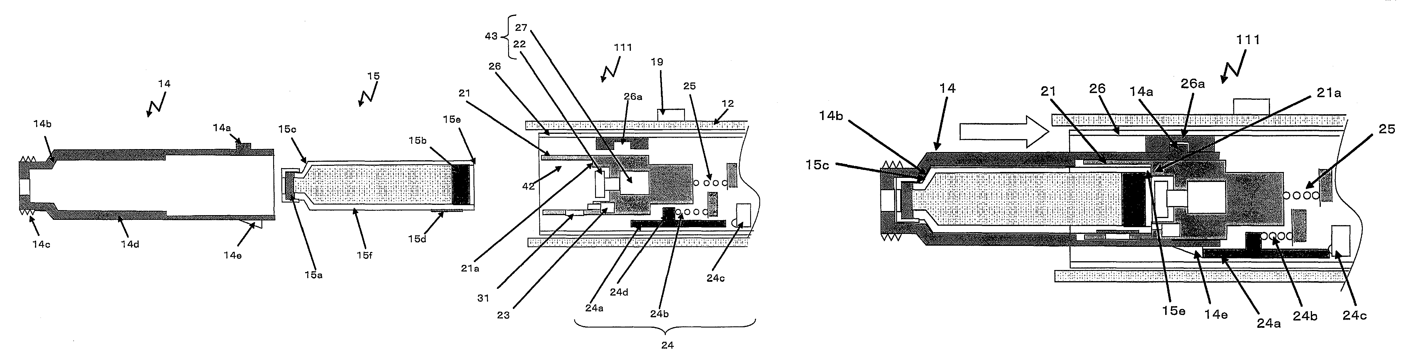
[0174]A medication administering device with which the needle was pulled out after the needle is tapped to a living body by electrically-driven means and injection of the preparation has been put to practical use in the past as a medication administering device for easily administering a preparation to a living body.

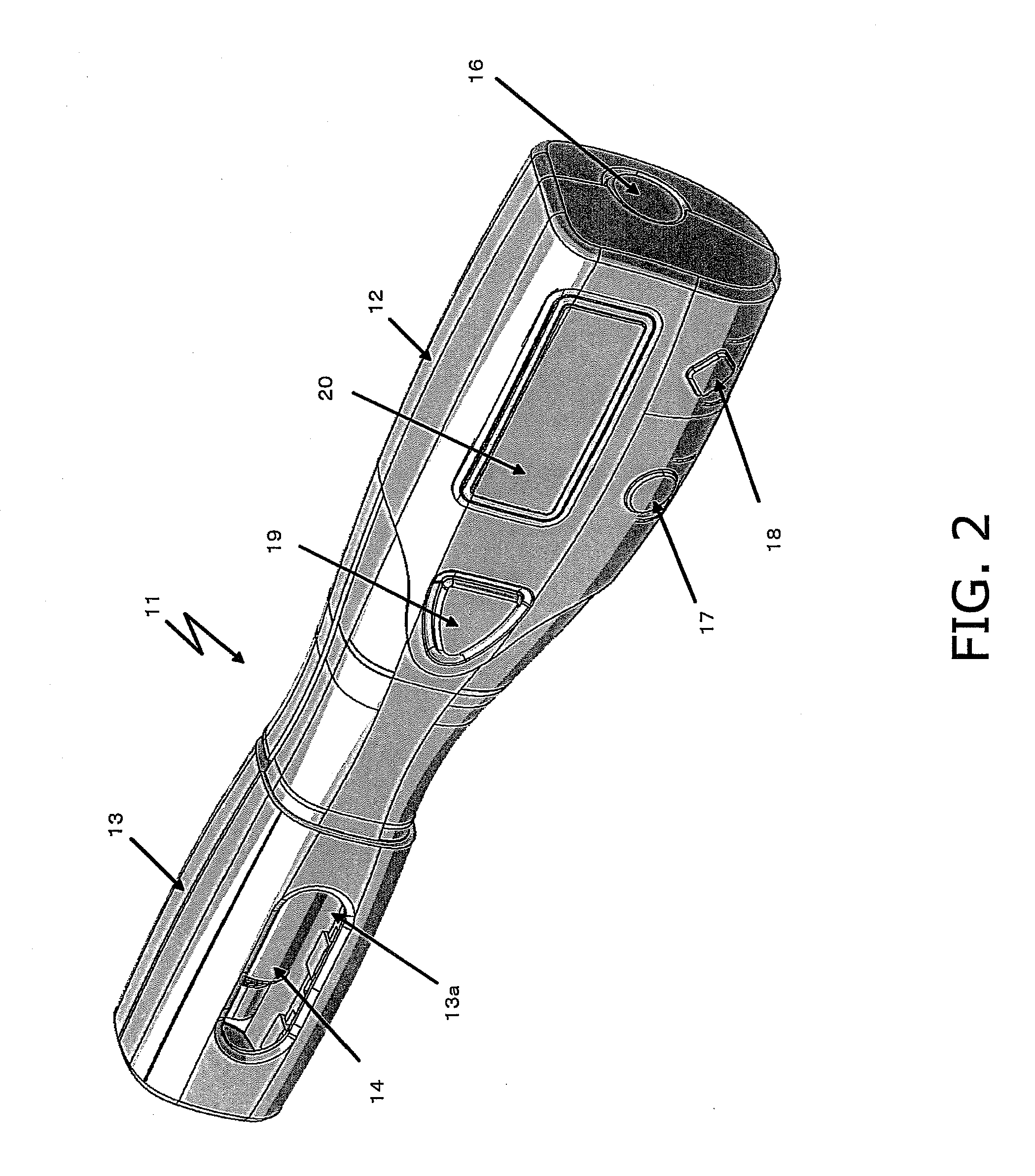
[0175]Specifically, as shown in FIGS. 22(a) to 22(c), when a medication administering device 1301 such as this is used, the user first mounts a syringe 1303a to a front case component 1303b, and then mounts this front component 1303 to a main body 1302 that includes a medication administering button 1302a for pushing out a piston 1302b. A preparation syringe 1303f has rubber seals (not shown) on the distal end side and the rear end side. The rubber seals are pressed and deformed in the distal end direction by the piston 1302b, and along with this deformation the preparation is injected into the living body. Also, the front case component 1303b is constituted by a front c...

reference example 2

[0211]A medication administering device with which the puncture needle was electrically inserted into the living body and then removed after injection of the preparation has been put to practical use in the past as a medication administering device for easily administering a preparation to a living body.

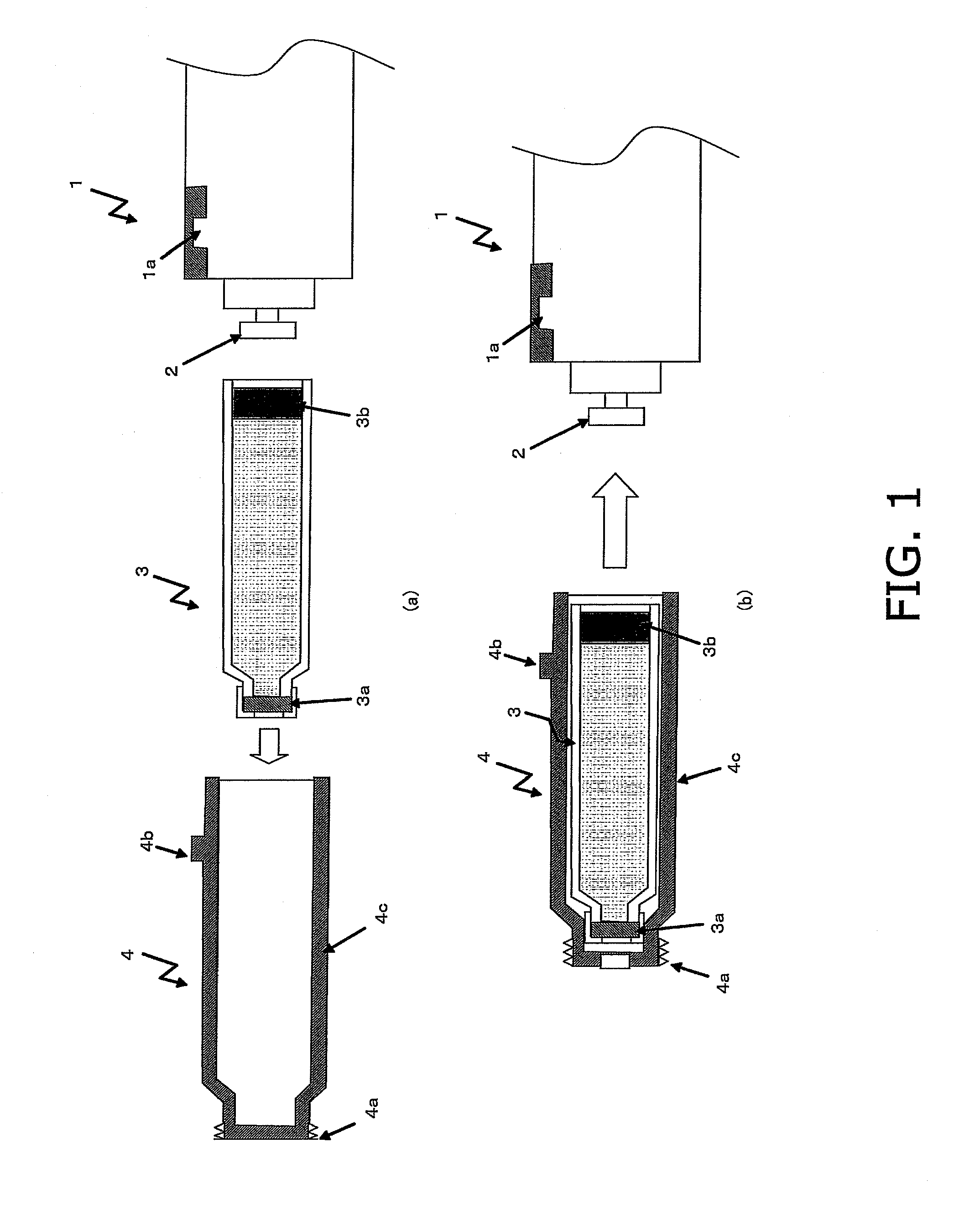
[0212]Specifically, as shown in FIG. 27(a), when this medication administering device 1401 is used, the user first docks a syringe 1403a and a front case component 1403b. In between these two, a slidably constituted front component 1403 is mounted to a main body 1402. At this point, a fastening groove 1403f formed at one end of the front case component 1403b allows the attachment and removal of the front case component 1403b and the main body 1402. The members constituted by the syringe 1403a and the members constituted by the main body 1402 are then linked, and the syringe 1403a is able to slide (not shown). A switch (not shown) that detects the attachment and removal of the front c...

reference example 3

[0247]A medication administering device with which the puncture needle was inserted electrically into a living body and then removed after the injection of the preparation has been put to practical use in the past as a medication administering device for easily administering a preparation to a living body.

[0248]Specifically, as shown in FIG. 33(a), when a medication administering device 1501 such as this is used, the user first docks a syringe 1503a and a front case component 1503b. In between these two, a slidably constituted front component 1503 is mounted to a main body 1502. At this point, a fastening groove 1503f formed at one end of the front case component 1503b allows the attachment and removal of the front case component 1503b and the main body 1502. The members constituted by the syringe 1503a and the members constituted by the main body 1502 are then linked, and the syringe 1503a is able to slide (not shown).

[0249]After this, a needle portion 1505 is rotated and attached ...


PUM


Abstract

A medication administering device has mounted thereto a preparation syringe containing a preparation and comprises a substantially cylindrical syringe cover that supports the preparation syringe on the inner peripheral face side, a piston that presses on the rear end of the preparation syringe, and a piston case that surrounds the piston, that guides the outer peripheral face of the syringe cover in the direction of the piston on the substantially cylindrical inner peripheral face side, and that is mounted in a state in which the syringe cover is removable. The medication administering device comprises a syringe holder that guides the outer peripheral face of the preparation syringe in the direction of the piston on the cylindrical inner peripheral face side, and whose outer peripheral face is removably fitted together with the inner peripheral face of the syringe cover. A medication administering device comprises a syringe cover for mounting a preparation syringe to a main body, and has uneven faces of different angles of inclination on the end face of the syringe cover.

Description

BACKGROUND OF THE INVENTION[0001]I. Technical Field[0002]The present invention relates to a medication administering device to which a preparation syringe containing a preparation is mounted, and which allows a preparation to be administered to a living body and attachment and removal of a medication administering device and a preparation syringe in more detail.[0003]II. Description of the Related Art[0004]Medication administering devices with which a needle is retracted after a living body has been manually punctured and a preparation injected have seen practical applications in the past as medication administering devices for easily administering a preparation to a living body.[0005]For example, Published Japanese Translation No.2002-502296 of the PCT international Publication (published Jan. 22, 2002) discloses a constitution in which a preparation syringe 3 containing a preparation is inserted into a syringe cover 4 as shown in FIG. 1(a), after which the syringe cover 4 is mount...

Claims


Application Information

Patent Timeline
Patent Type & Authority Patents(United States)
IPC IPC(8): A61M5/00A61M5/32
CPCA61M5/20A61M2005/2488A61M2005/2407A61M2205/6072A61M2005/3142A61M2005/244A61M2005/206A61M2005/2477A61M2205/6063A61M5/315A61M5/24A61M5/3202
Inventor IIO, TOSHIAKITAKABATAKE, YUKIHIROWATANABE, HIDENORIKIKUCHI, SEIJI
Owner PHC HLDG CORP
Why Eureka
Try Eureka