Particle detection

a particle detection and particle technology, applied in the field of particle detection, can solve the problems of general inability to distinguish detectors, slow calibration, and type i (false positive) errors of beam detectors

Active Publication Date: 2014-08-12
GARRETT THERMAL SYST LTD
View PDF59 Cites 20 Cited by
  • Summary
  • Abstract
  • Description
  • Claims
  • Application Information

AI Technical Summary

Benefits of technology

[0024]As will be appreciated, whilst the illustrative examples relate to the use of visible or near visible electromagnetic radiation the tem light can be seen as broadly encompassing the electromagnetic spectrum. However in the visible and near visible portions of the EM spectrum the challenges in practically and cheaply generating, controlling, focussing and receiving are minimised.
[0046]Advantageously, this arrangement can possess the advantage of a wide field sensor in terms of ease of alignment, and the advantage of narrow viewing angle sensors in terms of receiver noise.

Problems solved by technology

Firstly, beam detectors may suffer a type I (false positive) error where foreign objects or other particulate matter, such as dust, enters the monitored area and obscure the beam. Beam detectors are generally unable to distinguish between the obscuration caused by particles of interest e.g. smoke, and absorption which results from the presence of foreign body of no interest e.g. a bug flying into the beam.
Secondly, beam detectors may require careful alignment at the time of installation. Such alignment aims to ensure that in normal conditions, free from smoke, light enters the sensor so as to capture the majority of the transmitted beam, and to in turn maximise sensitivity to an obscuration. This calibration may be slow and therefore costly to perform. Moreover, it may need to be repeated as the physical environment that the detector occupies changes, for example because of small movements in the structure to which a beam detector is attached. In some cases, if the intensity of incident light on the detector diminishes quickly this misalignment may also cause a false alarm.
This reduces the effect that poor alignment between the beam and photodetector would otherwise have.
However, this solution comes at the cost of increased sensitivity to unwanted background light, which in turn complicates the detection process and increases the likelihood of failing to detect the presence of particles of interest.
Supplying power to the transmitters within a particle detection system can be costly.
There are practical / commercial limits on the amount of power that can be supplied.
The limited supply of power limits the optical power output of the transmitter, which in turn limits the signal to noise ratio of the measured signal.
If the signal to noise ratio of the system degrades too far, the system may experience frequent or continual false alarms.
This is undesirable.

Method used


Image

  • Particle detection
  • Particle detection
  • Particle detection

Examples


Embodiment Construction

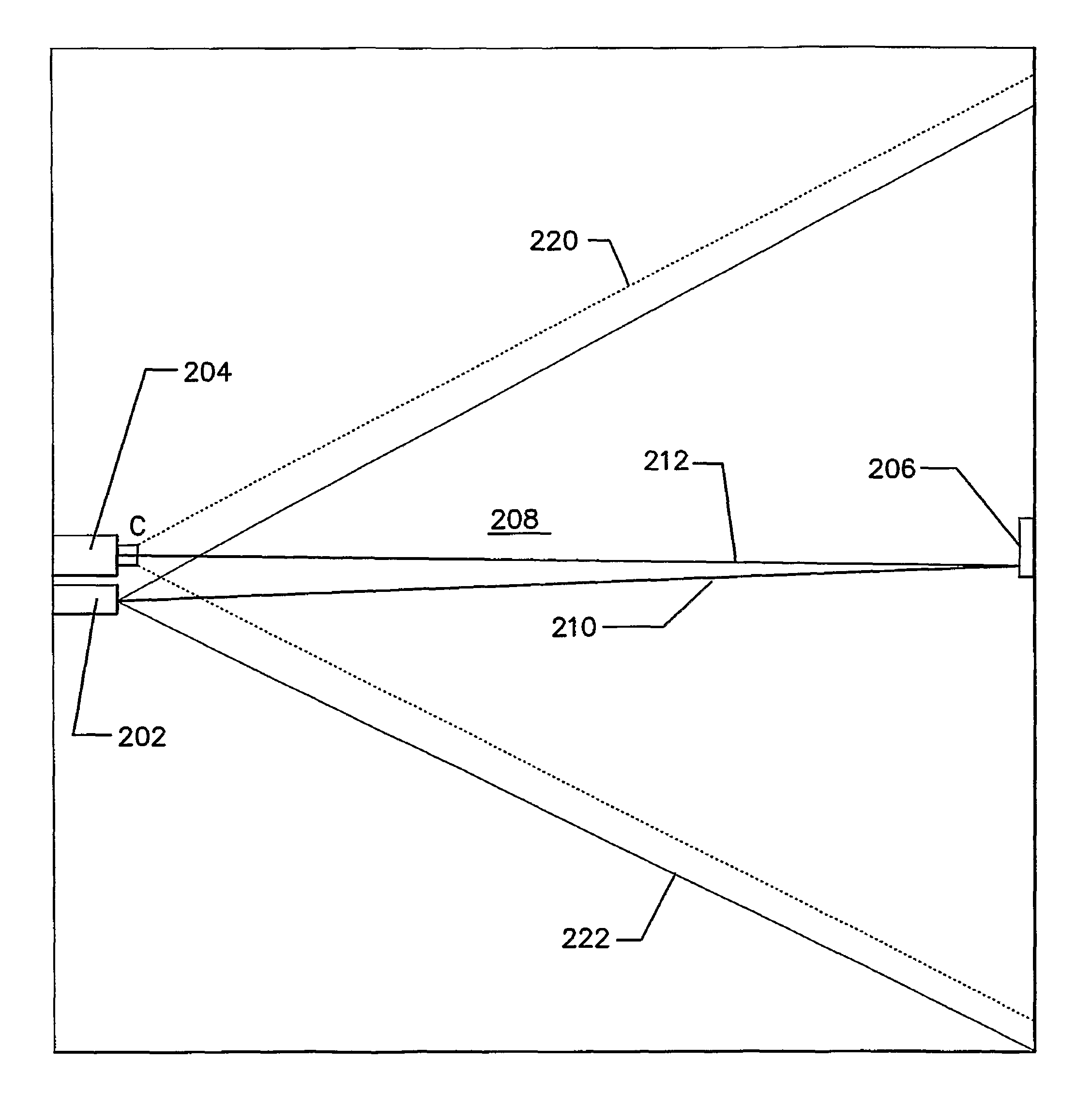
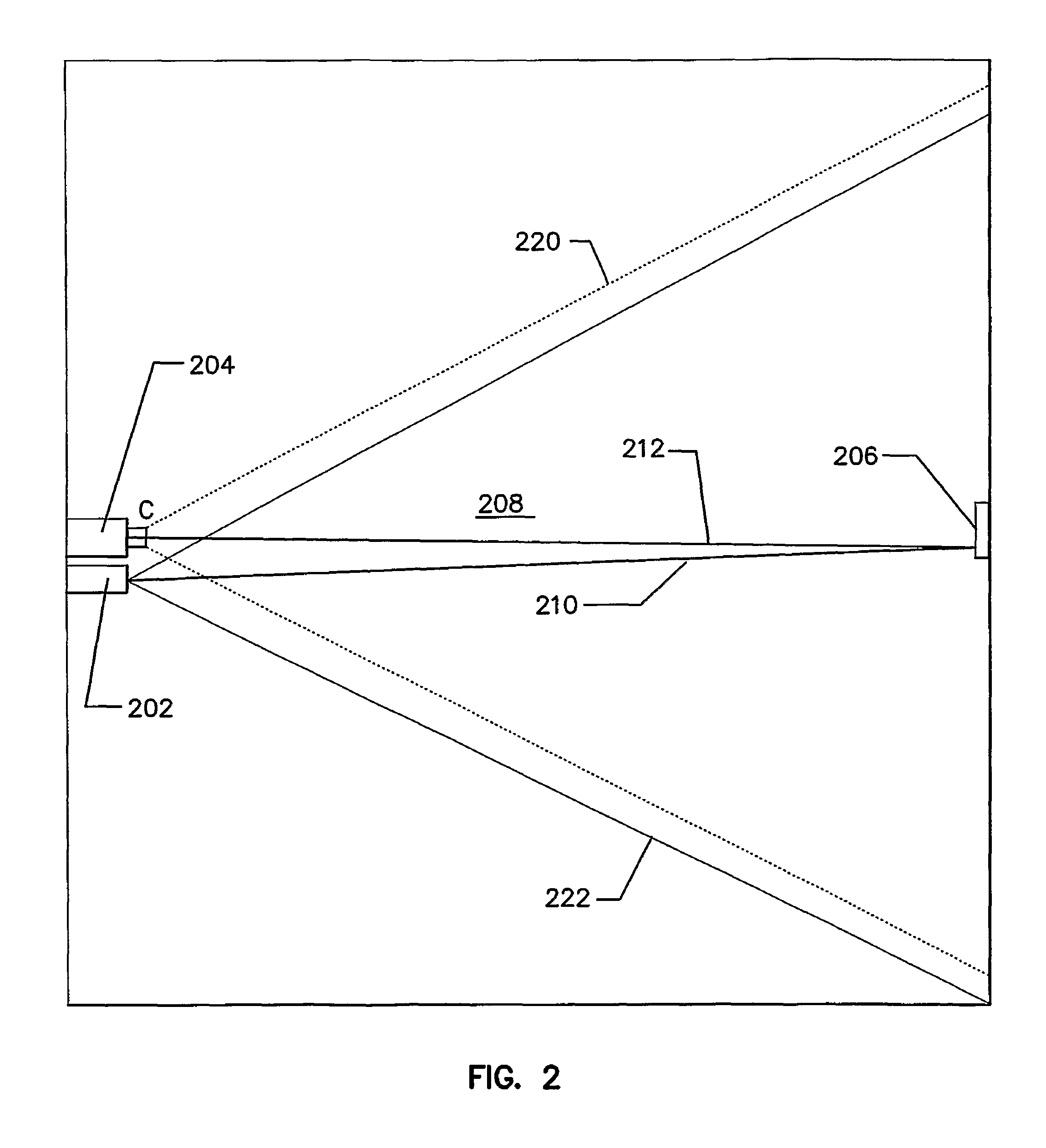
[0157]FIG. 2 shows an embodiment of the present invention. The detector 200 includes a light emitter 202, a receiver 204, and a target 206, acting in co-operation to detect particles in a monitored area 208. Target 206 reflects incident light 210 and thereby forms a light source and returns reflected light 212 to receiver 204. Preferably the target is a corner cube or other reflector adapted to reflect light back along its incident path, or other determined path.

[0158]The term light source as used is intended to be interpreted to include a device that actively produces an illumination from one or more (generally termed a light emitter or transmitter herein) as well as a reflector of an illumination generated by another device (generally termed a target or reflector herein).

[0159]In the preferred embodiment the receiver 204 is preferably a video camera or other receiver having an array of light sensors. A person skilled in the art would appreciate that receiver 204 may be constructed...


PUM

PropertyMeasurementUnit
field of viewaaaaaaaaaa
wavelengthaaaaaaaaaa

Abstract

A particle detection system including; at least one light source adapted to illuminate a volume being monitored at at least two wavelengths; a receiver having a field of view and being adapted to receive light from at least one light source after said light has traversed the volume being monitored and being adapted to generate signals indicative of the intensity of light received at regions within the field of view of the receiver; a processor associated with the receiver adapted to process the signals generated by the receiver to correlate light received at at least two wavelengths in corresponding regions within the field of view of the receiver and generate an output indicative of the relative level of light received at the two wavelengths.

Description

PRIORITY CLAIM TO RELATED APPLICATIONS[0001]This application is a national stage application under 35 U.S.C. §371 of PCT / AU2009 / 000727, filed Jun. 10, 2009, and published as WO 2009 / 149498 A1 on Dec. 17, 2009, which claims priority to Australian Application No. 2008902909, filed Jun. 10, 2008, and to Australian Application No. 2008903268, filed Jun. 26, 2008, and to Australian Application No. 2008903269, filed Jun. 26, 2008, and to Australian Application No. 2008903270, filed Jun. 26, 2008, and to Australian Application No. 2009901923, filed May 1, 2009, which applications and publication are incorporated herein by reference and made a part hereof in their entirety, and the benefit of priority of each of which is claimed herein.FIELD OF THE INVENTION[0002]The present invention relates to particle detection. It will be convenient to hereinafter describe the invention in the context of smoke detection, however it should be appreciated that the present invention is not limited to that ...

Claims


Application Information

Patent Timeline
Patent Type & Authority Patents(United States)
IPC IPC(8): G01N21/53G01N15/02G01N21/00
CPCG01N21/49G01N15/0227G01N21/53G01N21/538G08B17/107G01N15/0205G01N2201/0627G01N2201/062G01N2201/0633G08B17/113G01N21/00G01V8/10G01N2201/0621G01N2201/0696G01N15/1434
Inventor KNOX, RONBOETTGER, KARLAJAY, KEMAL
Owner GARRETT THERMAL SYST LTD
Why Eureka
Try Eureka