Engine Dynamic Load Leveling

a dynamic load and engine technology, applied in electrical control, machines/engines, non-mechanical valves, etc., can solve the problems of increasing combustion control challenges, limiting dynamic response, and difficult control of combustion process, so as to reduce efficiency benefits, increase emissions, and increase combustion control challenges

Active Publication Date: 2008-06-12
FORD GLOBAL TECH LLC
View PDF13 Cites 51 Cited by
  • Summary
  • Abstract
  • Description
  • Claims
  • Application Information

AI Technical Summary

Benefits of technology

[0006]However, the inventors herein have recognized disadvantages with this approach. Specifically, transition of a cylinder between combustion modes can increase combustion control challenges, reduce efficiency benefits from combustion ignition cylinders, and increase emissions, increase noise, vibration and harshness (NVH), and provide a less smooth torque delivery.

Problems solved by technology

In HCCI engines, ignition occurs virtually simultaneously throughout a combustion chamber as a result of compression instead of spark ignition, making the combustion process challenging to control.
The engine hardware used to control initial cylinder conditions such as internal residuals, intake air temperatures, and the combustion process stability window, limits dynamic response.
However, the inventors herein have recognized disadvantages with this approach.
Specifically, transition of a cylinder between combustion modes can increase combustion control challenges, reduce efficiency benefits from combustion ignition cylinders, and increase emissions, increase noise, vibration and harshness (NVH), and provide a less smooth torque delivery.

Method used


Image

  • Engine Dynamic Load Leveling
  • Engine Dynamic Load Leveling
  • Engine Dynamic Load Leveling

Examples


Embodiment Construction

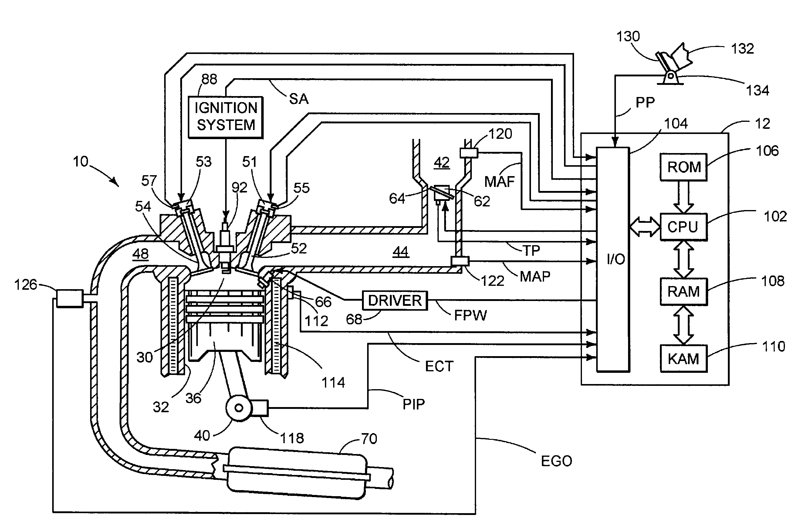
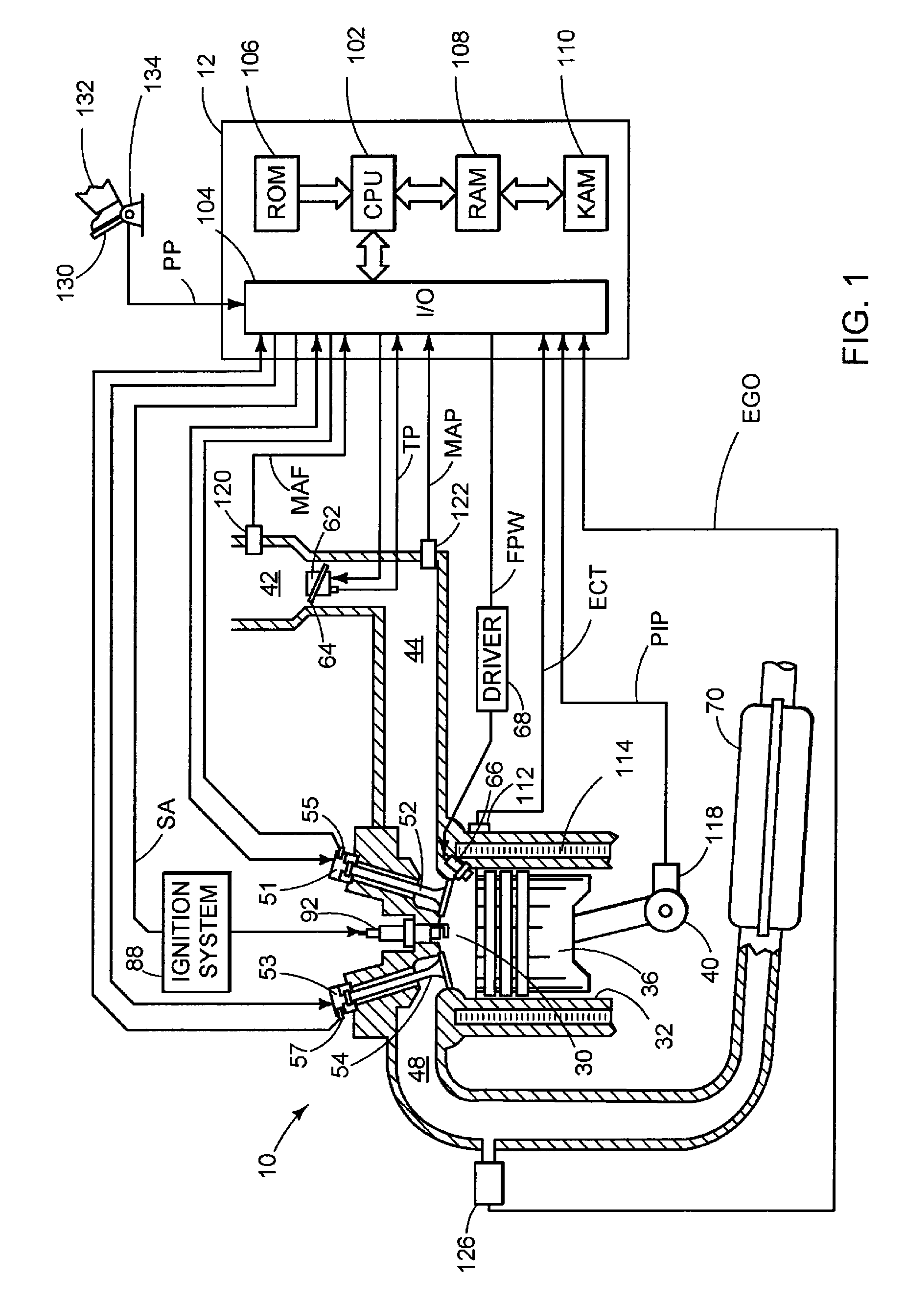
[0016]FIG. 1 is a schematic diagram showing one cylinder of multi-cylinder engine 10, which may be included in a propulsion system of an automobile. Engine 10 may be controlled at least partially by a control system including controller 12 and by input from a vehicle operator 132 via an input device 130. In this example, input device 130 includes an accelerator pedal and a pedal position sensor 134 for generating a proportional pedal position signal PP. Combustion chamber (i.e. cylinder) 30 of engine 10 may include combustion chamber walls 32 with piston 36 positioned therein. Piston 36 may be coupled to crankshaft 40 so that reciprocating motion of the piston is translated into rotational motion of the crankshaft. Crankshaft 40 may be coupled to at least one drive wheel of the passenger vehicle via a transmission system. Further, a starter motor may be coupled to crankshaft 40 via a flywheel to enable a starting operation of engine 10.

[0017]Combustion chamber 30 may receive intake ...


PUM


Abstract

A method for controlling an internal combustion engine having a plurality of cylinders using electronic valve actuation, including operating a first portion of the cylinders in a homogeneous charge compression ignition (HCCI) mode, operating a second portion of the cylinders in a non-HCCI mode, and adjusting the valve timing of the second portion of cylinders to dynamically load level the engine in response to a transient torque demand. A system for controlling a multiple cylinder internal combustion engine, including a first group of cylinders to operate in an HCCI mode, a second group of cylinders to operate in a non-HCCI mode, and an engine controller operably coupled to the first and second groups of cylinders, said controller to adjust the valve timing of the second group of cylinders to dynamically load level the engine in response to a transient torque demand.

Description

FIELD[0001]The present application relates to controlling dynamic load leveling in an engine.BACKGROUND AND SUMMARY[0002]Vehicles having an internal combustion engine can operate in a variety of modes. As one example, an engine may operate in a spark ignition (SI) mode, wherein a charge of a mixture of air and fuel is ignited by a spark performed by a sparking device within a combustion chamber. As another example, an engine may operate in a compression ignition mode, wherein a mixture of air and fuel are compressed within a combustion chamber by a piston, causing ignition of the charge without necessarily requiring the addition of a spark from a sparking device.[0003]One type of compression ignition known as homogeneous charge compression ignition (HCCI) utilizes compression of a substantially homogeneous mixture of air and fuel to achieve controlled auto-ignition (CAI). In HCCI engines, ignition occurs virtually simultaneously throughout a combustion chamber as a result of compres...

Claims


Application Information

Patent Timeline
Patent Type & Authority Applications(United States)
IPC IPC(8): F01L1/34F02D7/00F01L9/20
CPCF01L9/04Y02T10/18F01L2800/00F02B1/12F02B17/005F02B23/104F02B2075/125F02D13/0253F02D13/06F02D41/0082F02D41/0087F02D41/3035F02D2041/001F02D2250/21Y02T10/128Y02T10/123F01L2009/0426Y02T10/12F01L2009/2126F01L9/20
Inventor MICHELINI, JOHN O.KOLMANOVSKY, ILYA V.GIBSON, ALEX
Owner FORD GLOBAL TECH LLC
Why Eureka
Try Eureka