
Electromagnetic interference shield

a technology of electromagnetic interference shield and shielding device, which is applied in the direction of ventilation panel with screening provisions, casings/cabinets/drawers, electrical apparatus casings/cabinets/drawers, etc., which can solve the problem of affecting the operation of adjacent electrical equipment, electronic devices generating high levels of heat that must be dissipated, and the effectiveness of an emi shield tends to decreas

Inactive Publication Date: 2014-08-12
IBM CORP
View PDF17 Cites 8 Cited by
  • Summary
  • Abstract
  • Description
  • Claims
  • Application Information

AI Technical Summary

Problems solved by technology

Both of these types of interference generate electromagnetic fields that can interfere with the operation of adjacent electrical equipment.
However, electronic devices generate high levels of heat that must be dissipated for continued effective operation of the electronic devices.
While more airflow, and hence efficient cooling, is achieved with greater open areas, the effectiveness of an EMI shield tends to decrease as open area increases.

Method used


Image

  • Electromagnetic interference shield
  • Electromagnetic interference shield
  • Electromagnetic interference shield

Examples


Embodiment Construction

[0017]Detailed embodiments of the present invention are disclosed herein with reference to the accompanying drawings; however, it is to be understood that the disclosed embodiments are merely illustrative of potential embodiments of the invention and may take various forms. In addition, each of the examples given in connection with the various embodiments is also intended to be illustrative, and not restrictive. This description is intended to be interpreted merely as a representative basis for teaching one skilled in the art to variously employ the various aspects of the present disclosure. In the description, details of well-known features and techniques may be omitted to avoid unnecessarily obscuring the presented embodiments.

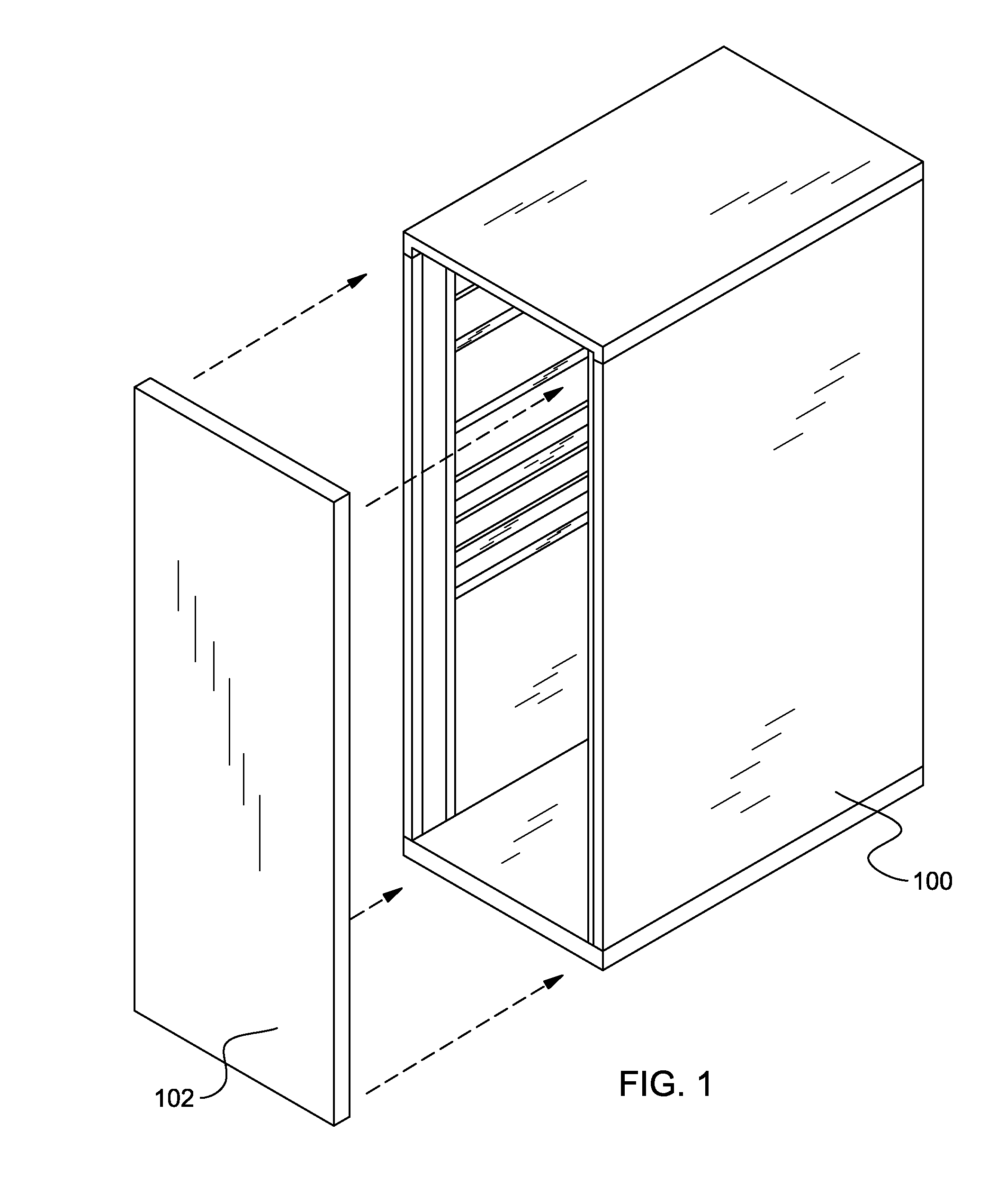
[0018]FIG. 1 depicts an electronic device enclosure in accordance with an embodiment of the present invention. In one embodiment, enclosure 100 is a server rack. In another embodiment, enclosure 100 is a computer tower. In other embodiments, enclosure 100 is...


PUM


Abstract

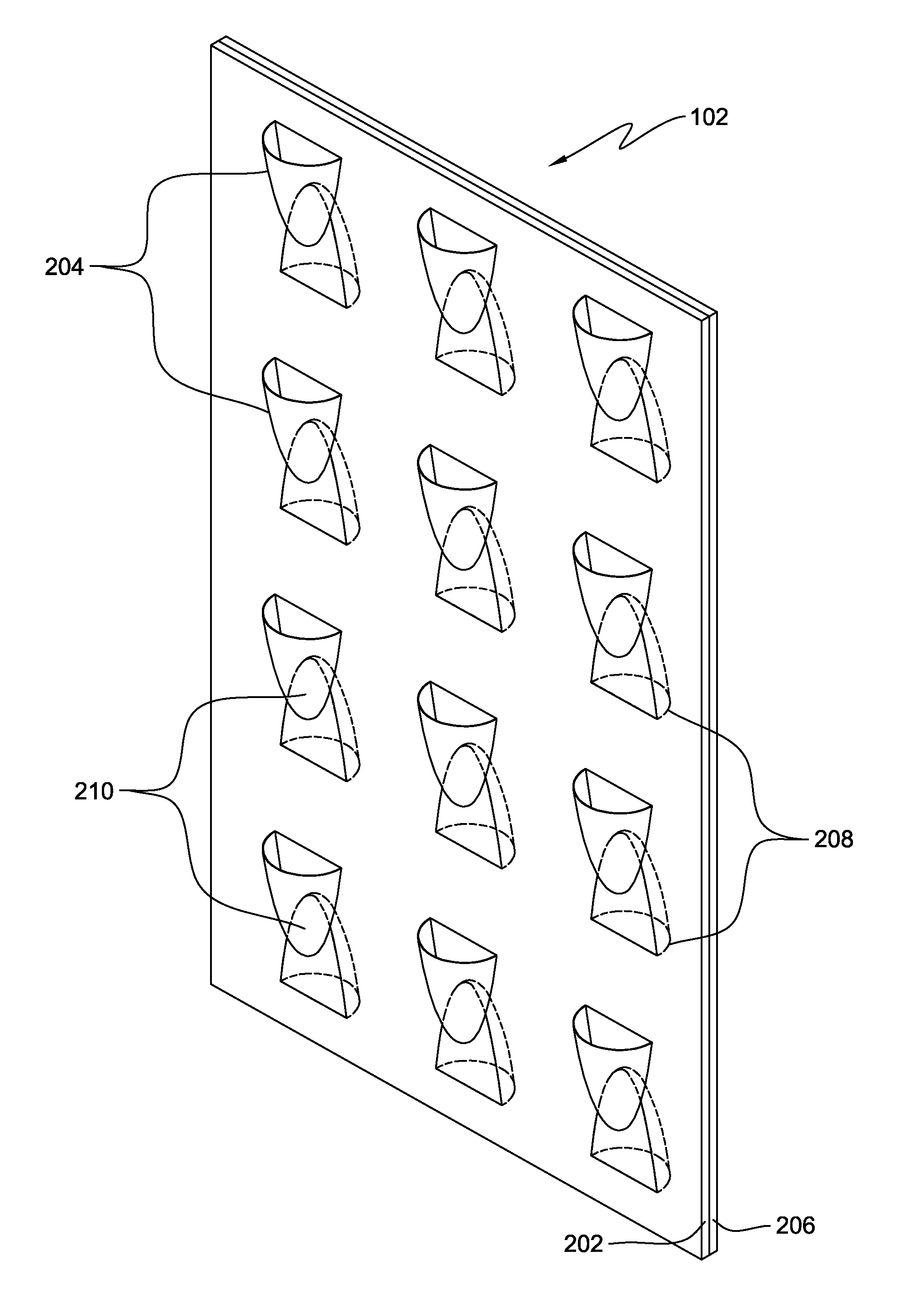
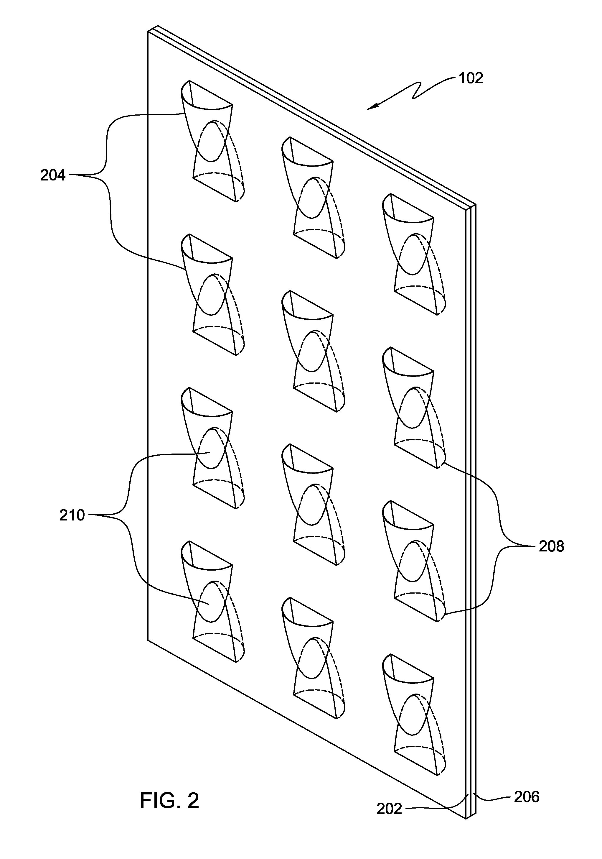
An electromagnetic interference (EMI) shield that increases the airflow through the EMI shield while preventing line-of-sight openings through the EMI shield. Two plates are coupled together. Each of the respective plates has a raised component with an aperture therethrough to provide a path through the plate. The raised component is preferably scoop-shaped with the aperture at one end and an opposite end tapering into the respective plate. At least a portion of one of the raised components overlaps at least a portion of the other of the raised components when the plates are coupled together to form a path through the plates, while the plates are coupled together. Line-of-sight openings through the plates, to an electronic device protected by the EMI shield, are at least partially prevented by the raised components.

Description

FIELD OF THE INVENTION[0001]This disclosure relates generally to shielding electronic devices from electromagnetic interference (EMI), and in particular, to systems which balance electromagnetic shielding with sufficient air flow.BACKGROUND OF THE INVENTION[0002]For purposes of this disclosure, the term electromagnetic interference (EMI) is understood to refer to electromagnetic emission and radiation that includes both electromagnetic interference and radio-frequency interference (RFI). Both of these types of interference generate electromagnetic fields that can interfere with the operation of adjacent electrical equipment. It is desirable to protect electronic devices from external EMI, and also to prevent internal EMI from escaping and possibly interfering with other electronic devices in the vicinity. To accomplish this, EMI shields are often used in enclosures containing electronic equipment, components, and / or circuitry (e.g., computers and test equipment).[0003]A solid EMI sh...

Claims


Application Information

Patent Timeline
Patent Type & Authority Patents(United States)
IPC IPC(8): H05K9/00H02G3/14H05K5/03
CPCH05K9/0041
Inventor GILLILAND, DON A.JOHNSON, DAVID B.MCMILLAN, TIMOTHY L.
Owner IBM CORP
Learn More