High force rotary actuator

a rotary actuator and high-force technology, applied in the direction of magnets, synchronous motors, magnets, etc., can solve the problems of increasing the size of the actuator system, sacrificing the output speed, and causing the actuator to over-proportion the allowable footprint area,

Active Publication Date: 2014-08-19
QM POWER
View PDF13 Cites 8 Cited by
  • Summary
  • Abstract
  • Description
  • Claims
  • Application Information

AI Technical Summary

Benefits of technology

[0007]An actuator includes an upper stator with four upper poles and a lower stator with four lower poles aligned with the four upper poles. A permanent magnet is attached to the upper stator and the lower stator. Four moving armatures are positioned at terminal ends of the four upper poles and the four lower poles. Coils are wrapped around the upper stator and the lower stator. A controller selectively applies current to the coils to migrate flux created by the permanent magnet through selective poles of the upper stator and the lower stator and thereby alter the size of air gaps associated with the four moving armatures.

Problems solved by technology

Although high forces can be produced using an electric motor and gearbox this comes at a sacrifice in output speed, which is proportional to the gearing ratio.
This increase in size not only adds to system weight, but typically exceeds the allowable footprint area for the actuator system.

Method used


Image

  • High force rotary actuator
  • High force rotary actuator
  • High force rotary actuator

Examples


Embodiment Construction

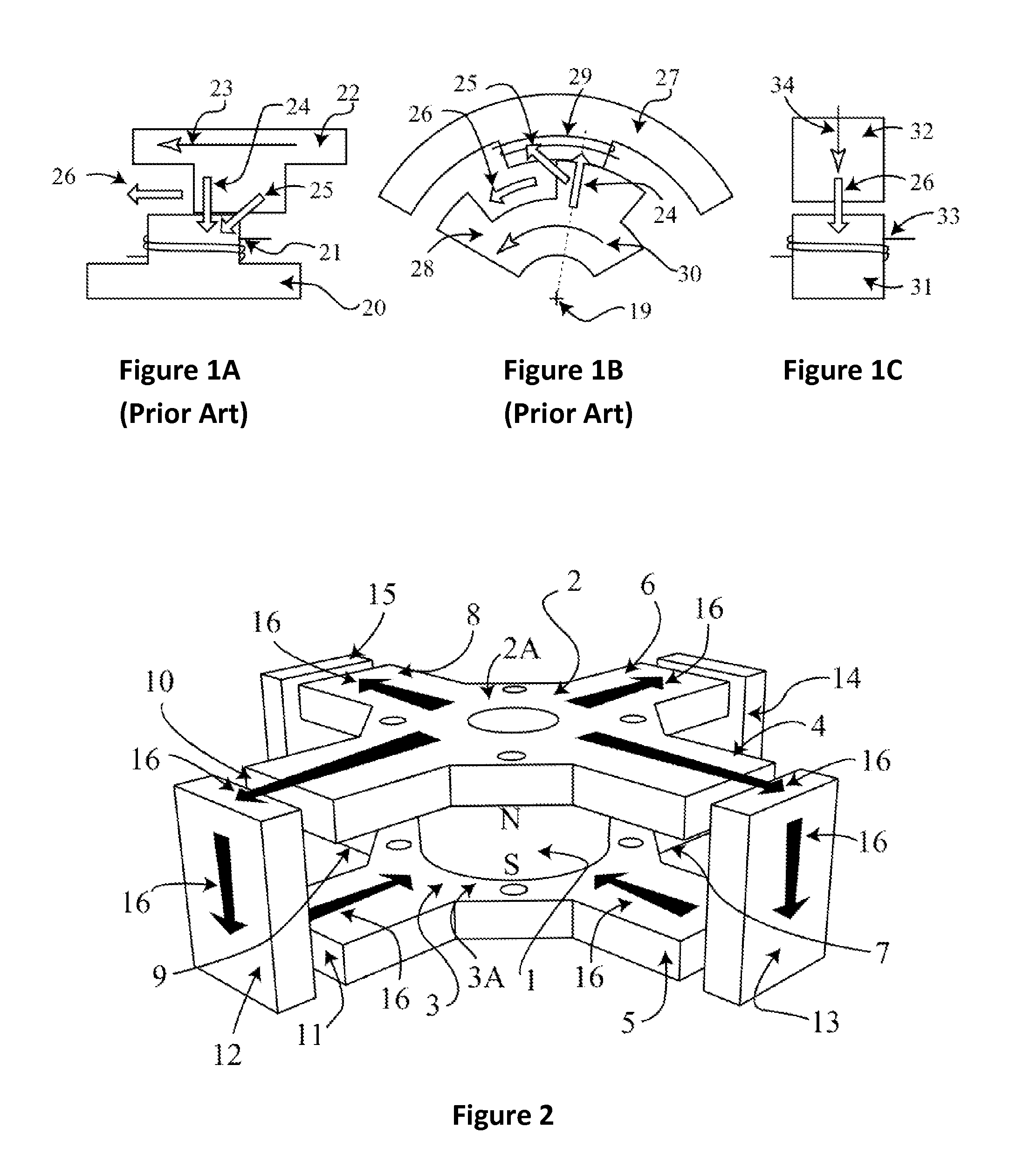
[0023]FIG. 1A shows a stator pole 20 for a conventional linear actuator. The stator pole 20 is composed from a magnetically soft material. A coil 21 is wrapped around the stator pole 20. The coil 21 is energized to magnetically attract the moving armature's pole 22, which is also composed from a magnetically soft material. The forces from the magnetic attraction have two main directions: one force 24 is perpendicular to the direction of motion 23 and the second main force 25 acts at an angular displacement to the direction of motion 23. The vector sum of the forces 24 and 25 forms a resultant or net force 26 acting in the direction of the motion 23, which will always be less than the sum of the forces 24 and 25. As the moving armature pole 22 moves into alignment with the stator pole 20, the force acting perpendicular to the direction of motion 24 becomes the dominant force, which reduces the net force 26.

[0024]FIG. 1B shows a stator pole 27 for a conventional rotary actuator compos...


PUM


Abstract

An actuator includes an upper stator with four upper poles and a lower stator with four lower poles aligned with the four upper poles. A permanent magnet is attached to the upper stator and the lower stator. Four moving armatures are positioned at terminal ends of the four upper poles and the four lower poles. Coils are wrapped around the upper stator and the lower stator. A controller selectively applies current to the coils to migrate flux created by the permanent magnet through selective poles of the upper stator and the lower stator and thereby alter the size of air gaps associated with the four moving armatures.

Description

CROSS-REFERENCE TO RELATED APPLICATION[0001]This application claims priority to U.S. Provisional Patent Application 61 / 325,259, filed Apr. 16, 2010, the contents of which are incorporated herein by reference.FIELD OF THE INVENTION[0002]This invention relates generally to devices to create motive forces. More particularly, this invention relates to a high force rotary actuator.BACKGROUND OF THE INVENTION[0003]Most applications requiring high forces, such as robotic arms and lifts, use hydraulic actuators to develop the required force to move a payload. A hydraulic actuator system requires a gas or electric motor driven pump, a reservoir, fluid lines and control valves operated either by hand or a microprocessor. It would be desirable to replace the hydraulic actuators and the ancillary components required to operate them in these applications with lightweight, high force electro-mechanical actuators.[0004]Hydraulic actuators provide a mechanical advantage not unlike a gearbox or a tr...

Claims


Application Information

Patent Timeline
Patent Type & Authority Patents(United States)
IPC IPC(8): H02K7/10H02K19/06
CPCH02K7/06H01F7/122H01F7/145H02K41/06H02K33/12H02K1/146H02K3/18
Inventor FLYNN, CHARLES, J.
Owner QM POWER
Why Eureka
Try Eureka