
Electromagnetic orientation system for deep wells

a technology of electromagnetic orientation and deep well, which is applied in the direction of instruments, borehole/well accessories, surveys, etc., can solve the problems of inability to determine the target field by the usual gravity measurement, and the target field is not precisely known

Active Publication Date: 2014-08-19
HALLIBURTON ENERGY SERVICES INC
View PDF7 Cites 24 Cited by
  • Summary
  • Abstract
  • Description
  • Claims
  • Application Information

AI Technical Summary

Benefits of technology

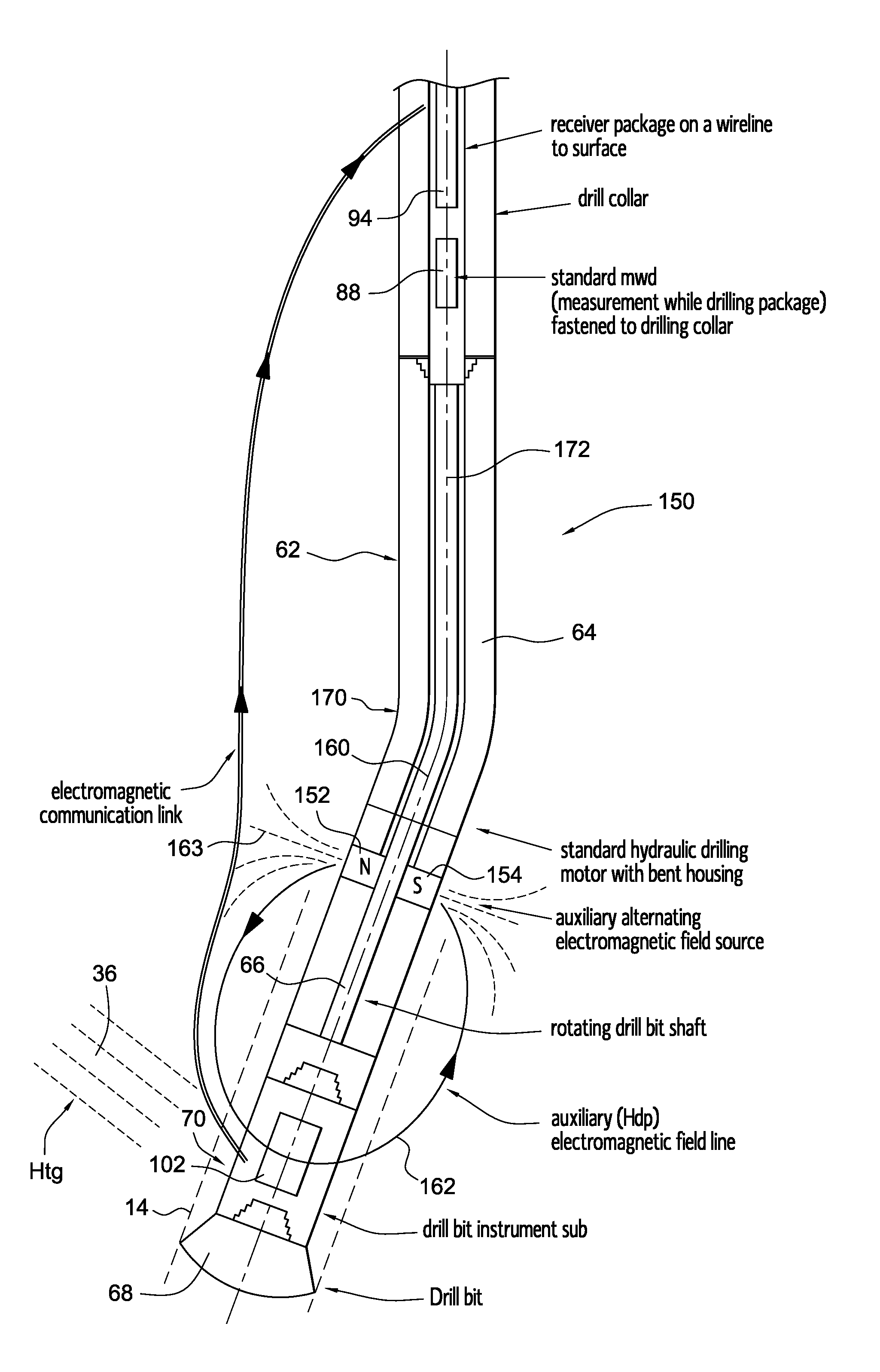
The present invention is about an electromagnetic method and device used to determine the position of a drill bit instrumentation sub, with respect to a borehole drilling assembly, where the instrument sub's axis is aligned with the direction of drilling. The invention involves using a dipole electromagnetic field source fastened to the drilling assembly to create an auxiliary alternating electromagnetic field with a perpendicular dipole axis to the borehole axis. The field lines generated by this magnet are measured by electromagnetic field sensors in the drill bit instrument sub. This approach, when used in conjunction with a prior art method, allows for the determination of the direction from a relief borehole to a target blowout well without using an intermediate parameter like gravity or the Earth's magnetic field.

Problems solved by technology

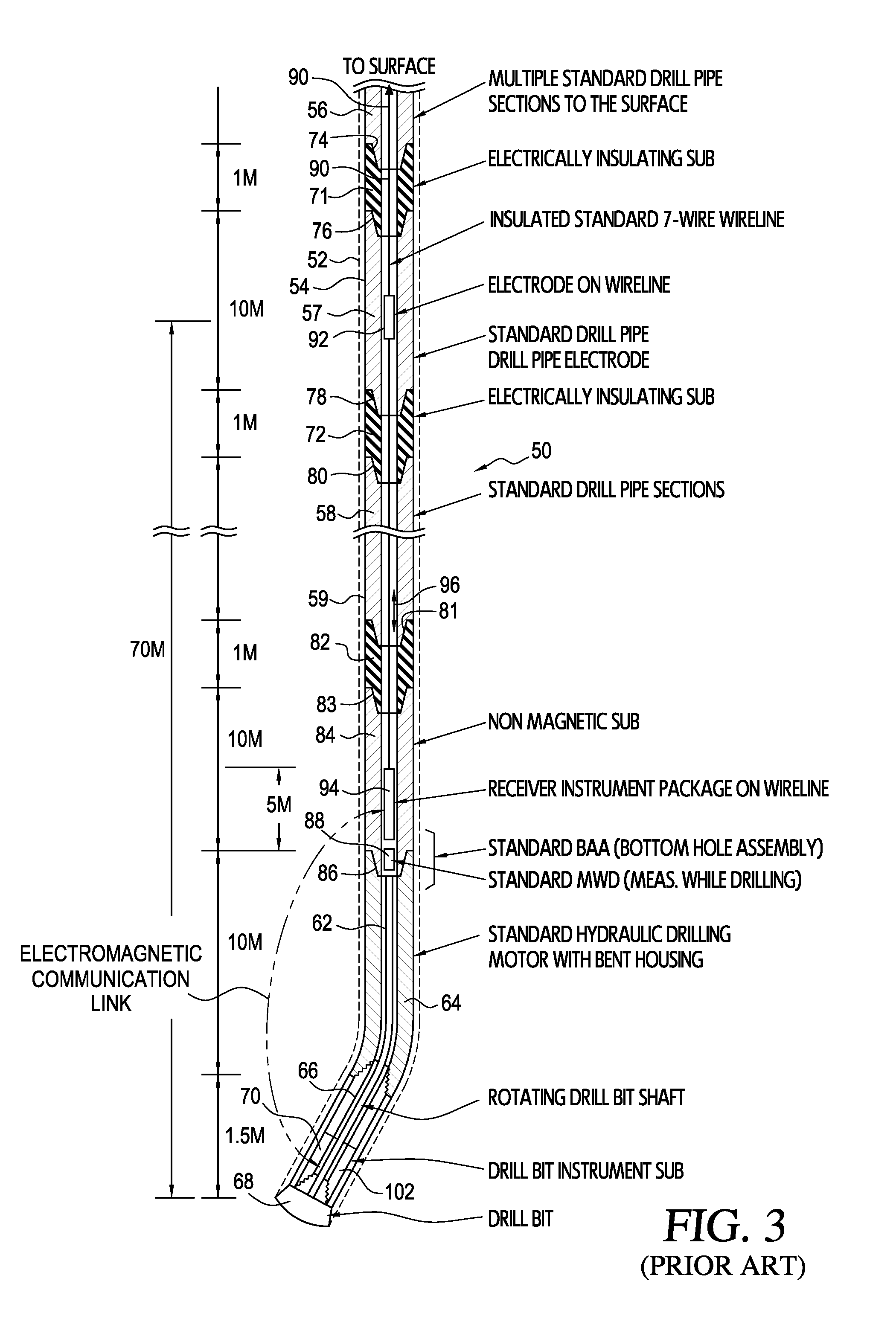
Measurement of the target electromagnetic field gives the azimuthal direction to the target well with respect to the instrument package; however, the azimuthal direction of the drilling motor axis with respect to the target field is not precisely known, and cannot be determined by the usual gravity measurements when the borehole being drilled is nearly vertical.

Method used


Image

  • Electromagnetic orientation system for deep wells
  • Electromagnetic orientation system for deep wells
  • Electromagnetic orientation system for deep wells

Examples


Embodiment Construction

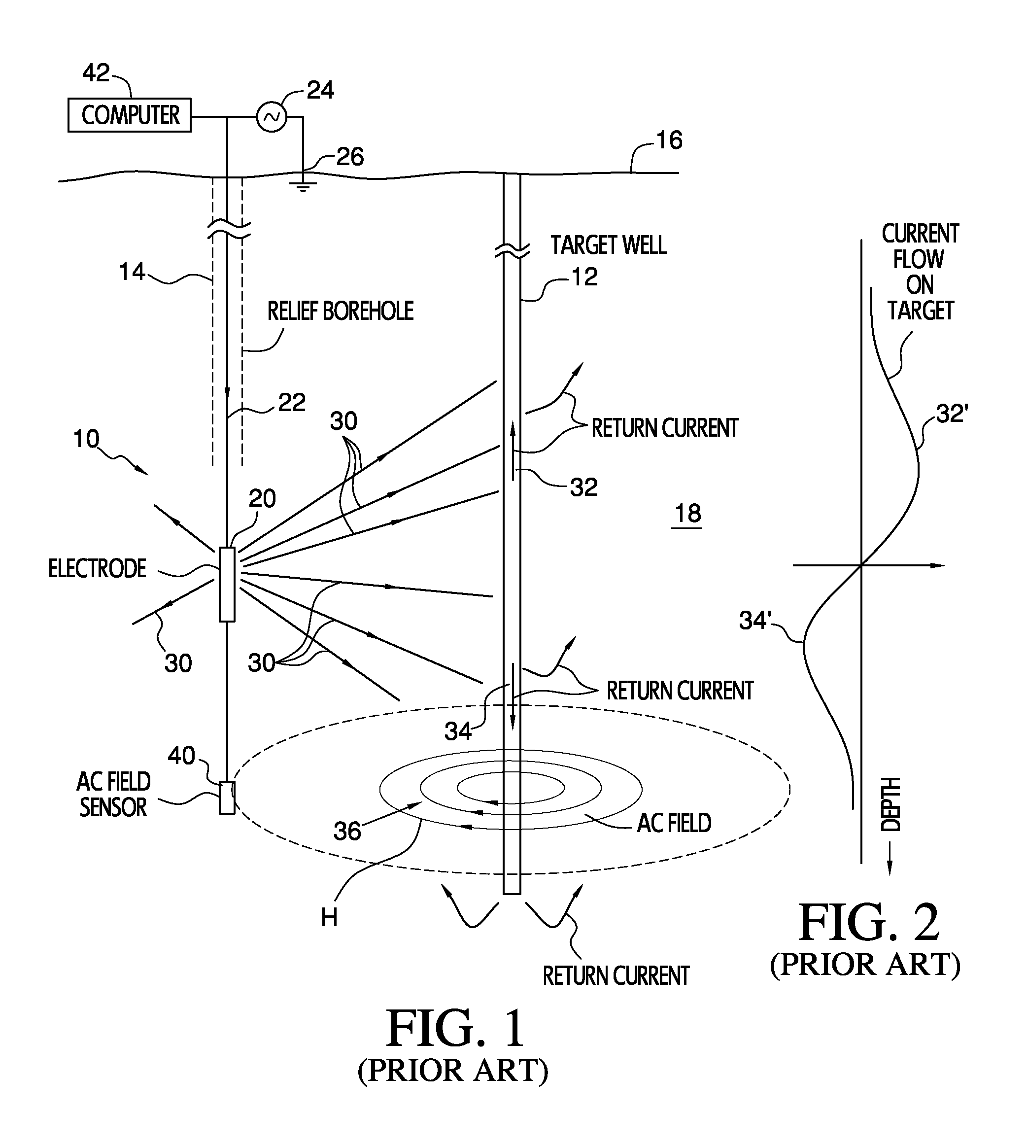
[0044]FIG. 1 illustrates, in diagrammatic form, a standard well locating system 10 such as that described in U.S. Pat. No. 4,700,142, the disclosure of which is hereby incorporated herein by reference. In such a system, a target well 12 is to be intersected by drilling a relief borehole, or well, 14 along a path that will intersect the target at a desired depth below the earth's surface 16. The target well is cased, or has a drill string or other electrically conductive material in it, so that electrical current flowing in the earth's formations 18 surrounding the well 12 will tend to be concentrated on that conductive material. An alternating electrical current is injected into the earth by an electrode 20 carried by a logging cable or wireline 22, which is lowered into the relief borehole 14 after the drill string that is used to drill the relief borehole has been pulled out. The electrode is connected through wireline 22 to one side of an AC source 24, the other side of which is ...


PUM


Abstract

An electromagnetic method and apparatus for determining the azimuthal orientation of a drill bit instrumentation sub (70), with respect to a borehole bottom drilling assembly (150) includes an electromagnet (152) fastened to the drilling assembly to produce an auxiliary alternating electromagnetic field (162) having an axis (163) that is perpendicular to the borehole axis (160). The direction of the field lines (162) generated by this magnet (152) and the simultaneous measurement of an electromagnetic field (36) generated by current flow in a blowout well casing is measured by electromagnetic field sensors in the drill bit instrument sub (70) to determine the direction to a blowout The direction of the auxiliary field (162) produced by the electromagnet (152) makes it possible to determine the direction to the blowout with reference to the direction of drilling without using an intermediate parameter such as, for example, the direction of gravity.

Description

CROSS REFERENCE TO RELATED APPLICATIONS[0001]This application claims the benefit of U.S. Provisional Patent Application No. 61 / 363,879, of Arthur F. Kuckes, filed Jul. 13, 2010, and entitled “Electromagnetic Orientation System for Deep Wells,” the disclosure of which is hereby incorporated herein in its entirety by reference. This application is also related to U.S. Patent Application Publication No. U.S.2010 / 0155138 A1 (the '138 publication), the disclosure of which is also hereby incorporated herein by reference.BACKGROUND OF THE INVENTION[0002]1. Field of the Invention[0003]The present invention relates, in general, to methods and apparatus for locating the distance and direction to a conductive target, such as a cased well or borehole, from a remote location such as a rescue borehole or well to obtain data for use in guiding the direction of drilling the rescue well to intersect the target, and to methods and apparatus for injecting time-varying electrical currents into the eart...

Claims


Application Information

Patent Timeline
Patent Type & Authority Patents(United States)
IPC IPC(8): G01V3/02E21B47/022
CPCE21B47/02216E21B47/0228
Inventor KUCKES, ARTHUR, F.
Owner HALLIBURTON ENERGY SERVICES INC
Learn More