Method for adjusting meshing position of hypoid gear

a meshing position and gear technology, applied in the direction of gearing, hoisting equipment, instruments, etc., can solve the problems of large transmission error and inability to identify accurate meshing positions, and achieve the effect of reducing gear noise, adjusting the meshing position with ease, and reducing gear nois

Active Publication Date: 2014-08-26
HONDA MOTOR CO LTD
View PDF20 Cites 3 Cited by
  • Summary
  • Abstract
  • Description
  • Claims
  • Application Information

AI Technical Summary

Benefits of technology

[0007]It is a general object of the present invention to provide a method of adjusting the meshing position of a hypoid gear for easily reducing gear noise.
[0008]A major object of the present invention is to provide a method of adjusting the meshing position of a hypoid gear for avoiding a large transmission error when the hypoid gear is in actual use.
[0016]By following the above process, it is possible to establish a more appropriate meshing position than to determine a meshing position where the first gear and the second gear mesh with each other based on only measured transmission errors according to the background art. Specifically, according to the present invention, the meshing position is established also in view of the hypothetical transmission errors in addition to the measured transmission errors. Consequently, gear noise is reduced. The above steps can be carried out by an arithmetic circuit, for example.
[0017]According to the present invention, as described above, in order to determine a meshing position, not only the measured transmission errors are used, but also the intervals between the measured transmission errors are interpolated with the hypothetical transmission errors. Therefore, it is possible to establish a more appropriate meshing position than to establish a meshing position based on only measured transmission errors. Consequently, gear noise is reduced.
[0018]Preferably, points of intersection between dividing lines with which the region is divided at various area ratios and the distances by which the second gear is displaced, are regarded as meshing positions of the second gear to set up a plurality of hypoid gears, the hypoid gears are judged for acceptance percentages, and the area ratio for an acceptance percentage of 90% or higher is determined and regarded as the given area ratio to establish the meshing position of the second gear. It is thus possible to establish a much more appropriate meshing position with ease.
[0019]Particularly, the area ratio for the acceptance percentage of 90% or higher is preferably determined while the hypoid gear is in actual usage conditions. Since the hypoid gear is evaluated in actual usage conditions, it is possible to establish the meshing position on the assumption that the first gear and the second gear are positionally displaced with respect to each other, for example. Therefore, it is possible to avoid a large transmission error when hypoid gears 10 of the same type are in actual use.

Problems solved by technology

The above method of adjusting the meshing position is disadvantageous in that since no transmission error is measured at any positions where the second gear is not assembled, the accurate meshing position cannot be identified unless the second gear is assembled at a position where the transmission error is truly minimum.
Another problem has been pointed out that when a hypoid gear is installed on an automotive body or the like and a torque is imposed thereon, the first gear and the second gear may be positionally displaced relatively to each other due to rigidity shortage of the gear case which houses the hypoid gear therein, resulting in a large transmission error.

Method used


Image

  • Method for adjusting meshing position of hypoid gear
  • Method for adjusting meshing position of hypoid gear
  • Method for adjusting meshing position of hypoid gear

Examples


Embodiment Construction

[0025]A method of adjusting the meshing position of a hypoid gear according to a preferred embodiment of the present invention will be described in detail below with reference to the accompanying drawings.

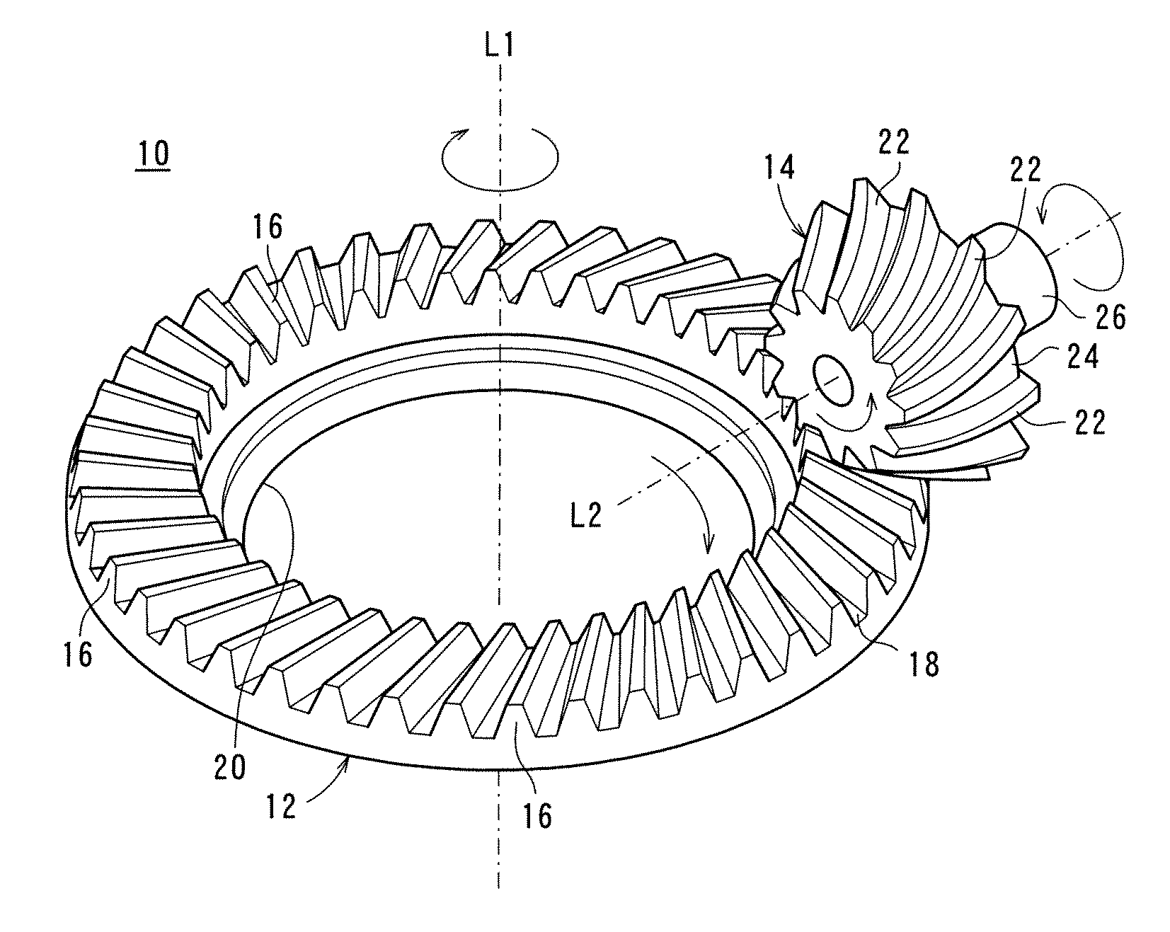
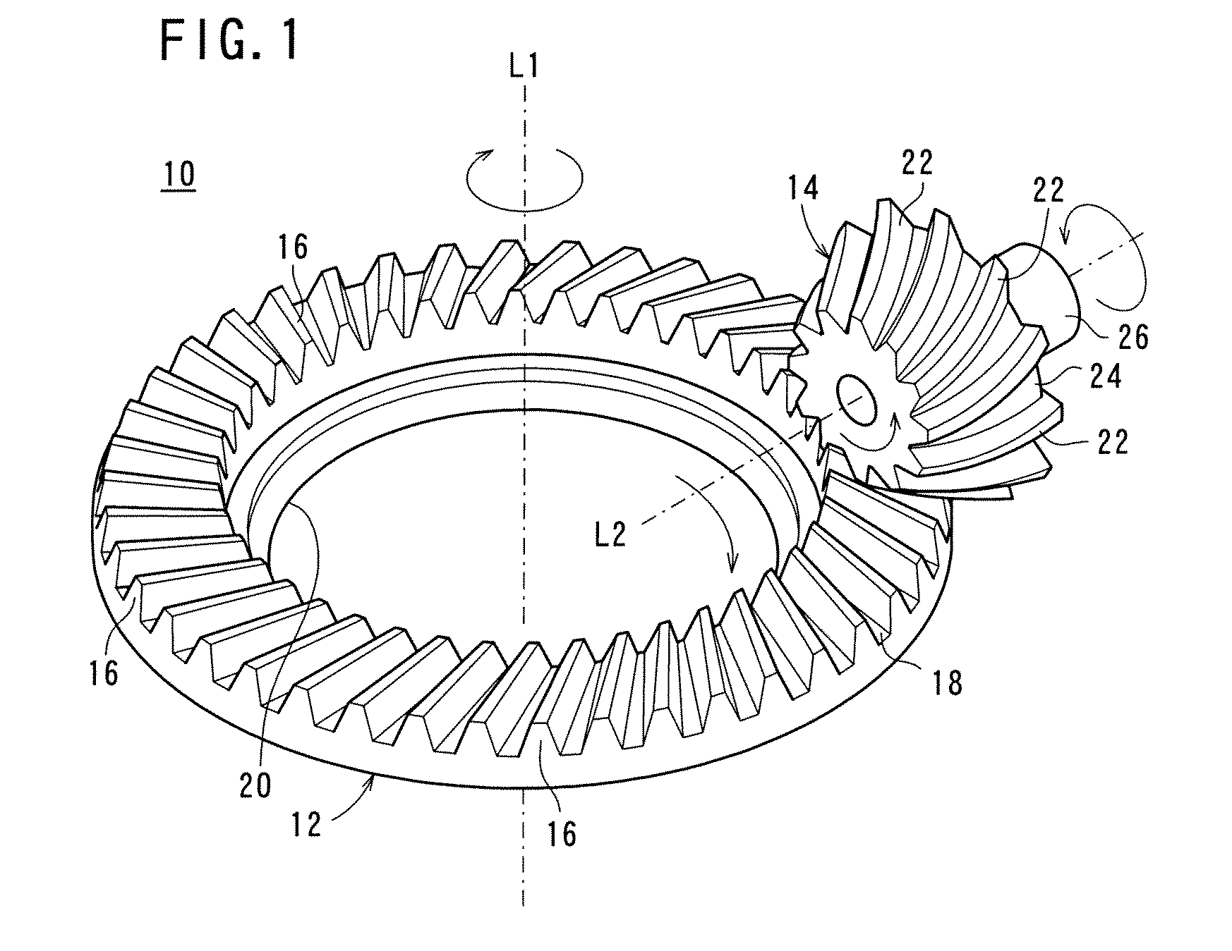
[0026]FIG. 1 is a schematic structural view of main parts of a hypoid gear 10. In this case, the hypoid gear 10 comprises a first gear 12 and a second gear 14 which is smaller in diameter than the first gear 12. In this case, the first gear 12 and the second gear 14 comprise spiral bevel gears.

[0027]The first gear 12 has an annular beveled portion 18 with teeth 16 disposed on a surface thereof. The beveled portion 18 has a through hole 20 defined therein, and a rotational shaft, not shown, is fitted in the through hole 20. The first gear 12 is rotatable about the rotational shaft (a hypothetical axis L1 in FIG. 1).

[0028]The second gear 14 has a beveled portion 24 with teeth 22 disposed thereon and a cylindrical shank 26 projecting from an end face of the beveled portion 24. The tee...


PUM


Abstract

A method for adjusting the meshing position of a hypoid gear having a first gear, and a second gear meshing with the first gear and transmitting the rotary motion thereof in the direction different from the extending direction of the axis of rotation of the first gear. The method for adjusting the meshing position comprises; a) a step for displacing the second gear a plurality of times along the axial direction of rotation while meshing with the first gear, b) a step for measuring the transmission error at each displacement position and plotting the relation of the displacement distance of the second gear and the measured transmission error, c) a step for evaluating the virtual transmission error between the measured transmission errors from the measured transmission error, d) a step for subtracting the measured transmission error and the virtual transmission error from a maximum allowable transmission error to determine the difference, e) a step for determining the area of a part surrounded by the difference and the maximum allowable transmission error by integrating the difference with the displacement distance of the second gear, and f) a step for dividing the part at a predetermined area ratio and setting a point where the division line intersects the displacement distance of the second gear at the meshing position of the second gear.

Description

TECHNICAL FIELD[0001]The present invention relates to a method of adjusting the meshing position of a hypoid gear including a first gear and a second gear which meshes with the first gear for transmitting the rotary motion of the first gear in a direction which is different from the direction along which the rotational shaft of the first gear extends.BACKGROUND ART[0002]A hypoid gear includes a first gear and a second gear that are held in mesh with each other. The first gear and the second gear comprise helical bevel gears, for example, and are held in mesh with each other such that their rotational shafts are offset from each other. Since the first gear and the second gear are held in mesh with each other, the rotary motion of the first gear can be transmitted to the second gear.[0003]The hypoid gear produces gear noise due to a mesh-dependent transmission error. According to Patent Document 1, it has been proposed to measure transmission errors at various assembled positions (mes...

Claims


Application Information

Patent Timeline
Patent Type & Authority Patents(United States)
IPC IPC(8): F16H35/06F16H1/14F16H55/20F16H57/022G01M13/02
CPCF16H1/145G01M13/021F16H57/022F16H55/20F16H2057/0221Y10T74/1956
Inventor KAWAKATSU, TSUTOMUTAKEUCHI, YASUOKOMABA, HIDEKIYOSHIBA, YUTAKAHASHIMOTO, NORIKAZU
Owner HONDA MOTOR CO LTD
Why Eureka
Try Eureka