
Arrangement and a method for monitoring an air flow in a drill rig

a technology of drill rig and air flow, which is applied in the direction of surveying, drilling pipes, borehole/well accessories, etc., can solve the problems of reducing drilling efficiency, reducing drilling efficiency, and substantially increasing the risk of plugged holes, so as to improve the accuracy of drilling and measuring the reduced system pressure, the effect of improving the accuracy of drilling

Active Publication Date: 2014-08-26
EPIROC ROCK DRILLS AB +1
View PDF15 Cites 3 Cited by
  • Summary
  • Abstract
  • Description
  • Claims
  • Application Information

AI Technical Summary

Benefits of technology

[0013]The solution according to the invention makes it possible to arrange a point for monitoring the flow of air through the flushing holes in the drill bit upstream of the compressor. Through measuring the reduced system pressure and knowing the inlet valve, the air flow rate through the system is indirectly monitored.
[0019]Additionally, it is practically easier to measure the reduced system pressure between the regulator and the inlet valve than between the inlet valve and the compressor. Further, the pressure between the inlet valve and the compressor is a negative pressure and measuring a negative pressure demands a more complicated and expensive equipment.
[0020]The solution according to the invention makes it possible to use relatively inexpensive standard sensors because resolution and accuracy of the sensor is not required to achieve same or better performance for the same air monitoring functions. This results in an arrangement having better performance at a lower price since pressure sensors provide reliable measuring results, and are less complex components that are readily available and easy to install.
[0021]A further advantage is that the amount of components is reduced compared to prior art solutions e.g. there is no device giving rise to a pressure drop in the air flow path. This has a positive impact on the energy consumption.

Problems solved by technology

This secondary breakage is not wanted because of the considerable quantity of waste energy and reduced drilling efficiency.
The ground condition where the rock drill works varies widely and the existence of mud in the ground substantially increases the risk of plugged holes.
When the flushing holes are plugged, the drill bit gets stuck and then the drilling is completely stopped.
Then, the drill hole must be cleaned which takes a considerable time.
This kind of electrical and / or mechanical devices are very expensive and have high maintenance cost.
Furthermore, prior art monitoring devices give rise to a pressure drop in the air flow path which will have a negative impact on the air flow out through the flushing holes in the drill bit.
It also has a negative impact on energy consumption.

Method used


Image

  • Arrangement and a method for monitoring an air flow in a drill rig
  • Arrangement and a method for monitoring an air flow in a drill rig
  • Arrangement and a method for monitoring an air flow in a drill rig

Examples


Embodiment Construction

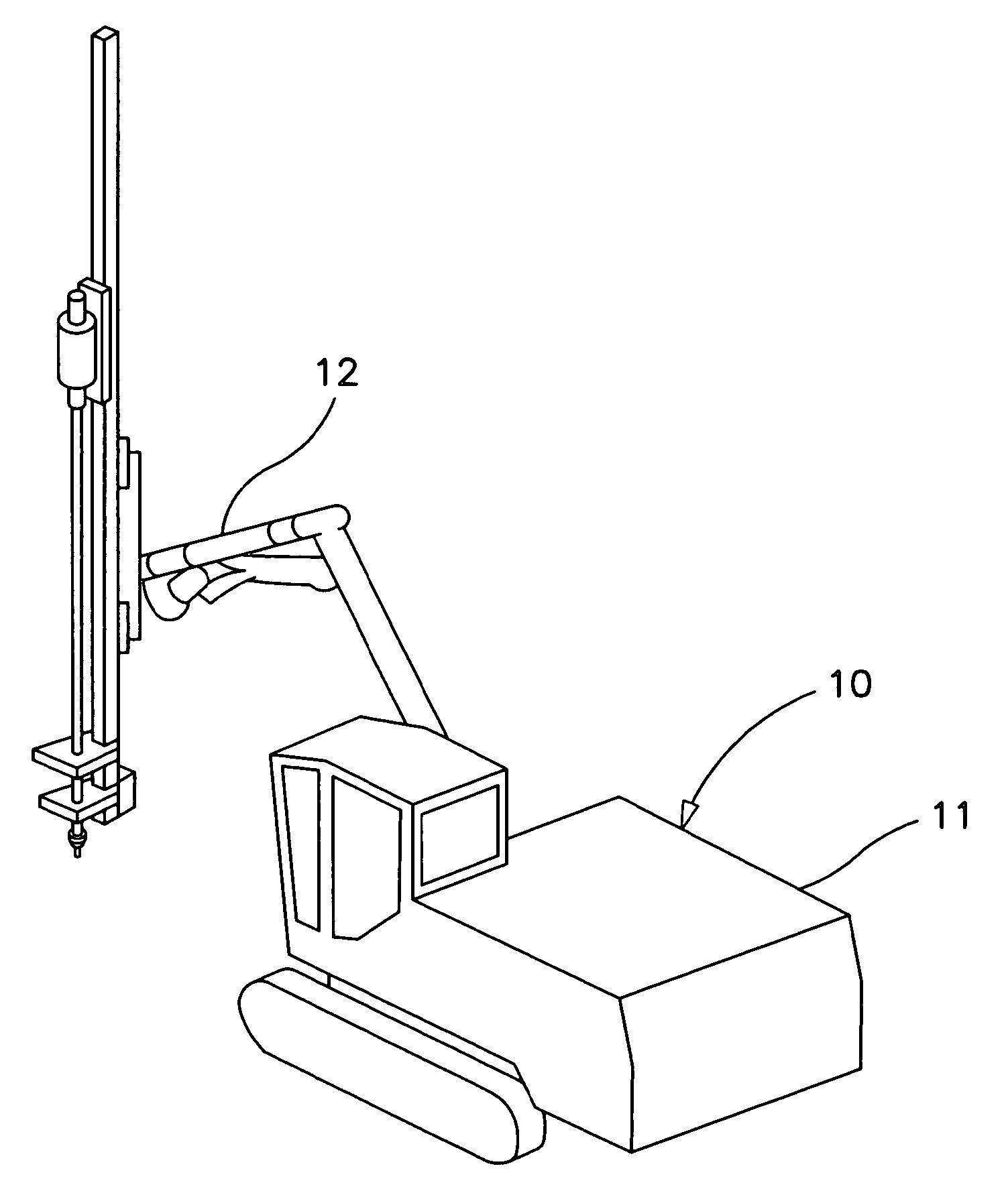
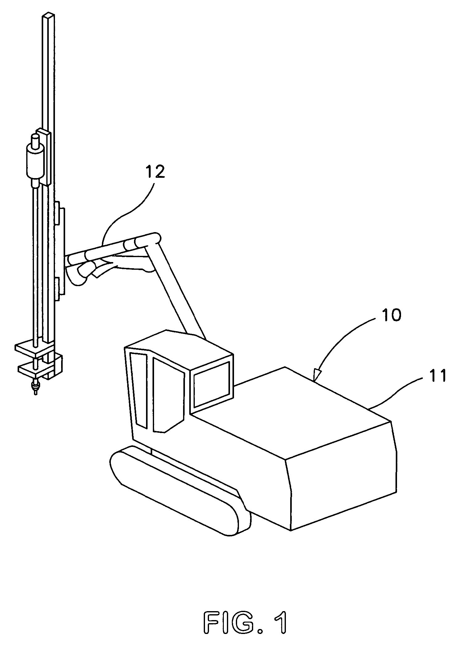
[0034]In FIG. 1 a surface rock drill rig 10 is illustrated. The rig 10 is used for hole drilling in different types of constructional or mining work. The rig 10 comprises a rig body 11 that comprises machinery for enabling transport of the rig, as well as for providing the required power to conduct the drilling and a displacement compressor (not shown). The drill is placed in the outer end of an elongated arm 12 that extend forward from the rig body 11. The arm is manoeuvrable to be easily movable to the intended position of the hole.

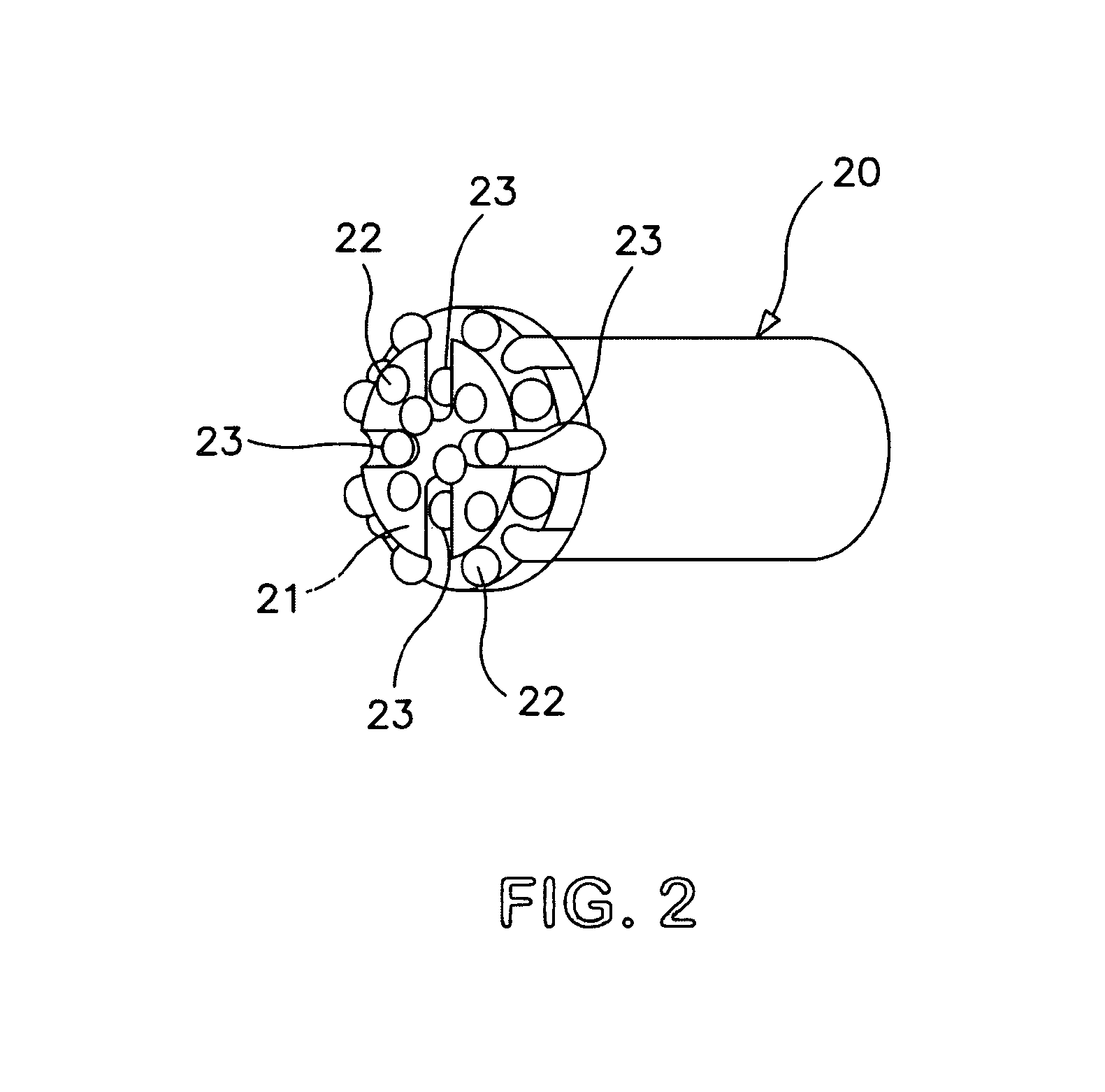
[0035]A drill bit 20, illustrated in FIG. 2, is used for penetrating the rock and chip away the fractured rocks. The front surface 21 of the drill bit 20 is provided with a number of drill elements 22 used for penetrating the rock. The front surface is furthermore provided with four flushing holes 23. Compressed air, provided from the displacement compressor in the rig body 11, is flowing out from the flushing holes 23 in order to blow the rock cuttings...


PUM


Abstract

An arrangement in a rock drill rig 10 has an inlet valve 31 arranged upstream from a displacement compressor 32 that is used for supplying an air flow 34 to at least one flushing hole 23 in the surface of a drill bit 20. The rock drill rig 10 also has an air regulator 35 arranged to regulate the system pressure in the air flow path 34 downstream from the compressor and a detector for detecting air flow through the at least one flushing hole 23 in the surface of the drill bit. The detector has a pressure sensor 36, arranged between the air regulator 35 and the inlet valve 31, for measuring the reduced system pressure.

Description

[0001]The present application claims the benefit of International Patent Application PCT / US2008 / 006075, filed in the United States Receiving Office on May 13, 2008, pursuant to 35 U.S.C. Section 365.TECHNICAL FIELD[0002]The present invention relates to an arrangement in a drill rig and to a method of detecting a reduced air flow through a flushing hole in a drill bit.BACKGROUND ART[0003]Drill rigs indifferent sizes are frequently used in constructional work to drill holes in rocks. The drill rig comprises a rock drilling machine with a drill bit adapted for the specific conditions of the rock and used to penetrate the rock, and chip away the fractured rocks. The penetration force is generated by either a high level feed force or percussive wave forms. The rotation torque generated by a rotation motor will shear off the fractured rock.[0004]In surface rock drilling processes, it is standard practice to use compressed air to blow away the rock cuttings and clean the surface of the roc...

Claims


Application Information

Patent Timeline
Patent Type & Authority Patents(United States)
IPC IPC(8): E21B21/08E21B21/16E21B7/02E21B44/02
CPCE21B7/022E21B21/16E21B44/02E21B21/08
Inventor JIAO, DEYIKRAINER, PER
Owner EPIROC ROCK DRILLS AB
Learn More