On-chip fluid recirculation pump for micro-fluid applications

a microfluid and fluid recirculation technology, applied in printing, inking apparatus, other printing apparatus, etc., can solve the problems of wasting a quarter to a half or more the imaging device's maintenance operation is notoriously wasteful, and the consumption wastes a quarter to a half of the fluid supply of the page-wide imaging device. , to achieve the effect of avoiding wasteful fluid spitting, minimizing operational

Active Publication Date: 2014-08-26
SHANGHAI AUREFLUIDICS TECH CO LTD
View PDF11 Cites 27 Cited by
  • Summary
  • Abstract
  • Description
  • Claims
  • Application Information

AI Technical Summary

Benefits of technology

[0007]The above-mentioned and other problems become solved with an on-chip fluid recirculation pump for micro-fluid applications. The embodiments include circulating fresh fluid (ink) through ejection chambers to ready them to fire while minimizing operational maintenance. Fresh flowing ink fights evaporation, avoids wasteful fluid spitting during maintenance and extends printhead life. The improvements are especially useful when implemented in an imaging device having a page-wide printhead array.

Problems solved by technology

In any configuration, imaging devices notoriously waste ink during maintenance operations.
The larger the printhead, the more the imaging device wastes it.
The consumption wastes a quarter to a half or more of a page-wide imaging device's fluid supply on maintenance alone.
Any devised solutions must also appreciate that these maintenance routines prematurely shorten the life of printheads.
During uncapped times, however, evaporation can occur so rapidly that imaging devices with scanning printheads periodically conduct maintenance jetting of unused nozzles when they pass outside the width of the print media at the end of a scan line.
Unfortunately, page-wide printheads can never scan outside the boundaries of an imaging width of a print media and cannot be jetted at ends of scan lines during times of nozzle uncapping like their scanning head counterparts.
This unfortunately further shortens the life of jetting actuators.

Method used


Image

  • On-chip fluid recirculation pump for micro-fluid applications
  • On-chip fluid recirculation pump for micro-fluid applications
  • On-chip fluid recirculation pump for micro-fluid applications

Examples


Embodiment Construction

[0017]In the following detailed description, reference is made to the accompanying drawings where like numerals represent like details. The embodiments are described in sufficient detail to enable those skilled in the art to practice the invention. It is to be understood that other embodiments may be utilized and that process, electrical, and mechanical changes, etc., may be made without departing from the scope of the invention. The following detailed description, therefore, is not to be taken in a limiting sense and the scope of the invention is defined only by the appended claims and their equivalents. In accordance with the present invention, methods and apparatus teach on-chip fluid recirculation pump(s) for micro-fluid applications, such as inkjet printing.

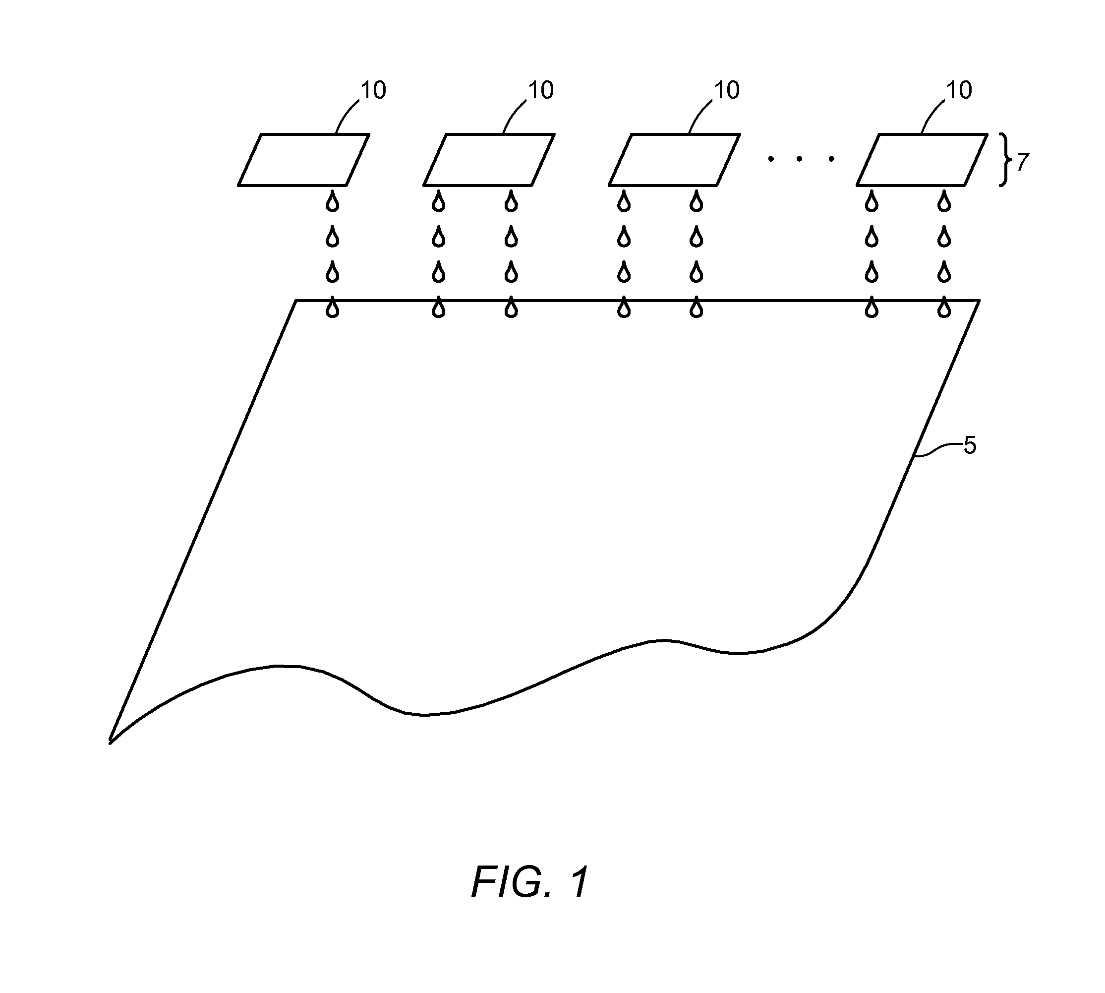
[0018]With reference to FIG. 1, pluralities of ejection chips 10 are configured in an array 7 across a print media 5 to ejection fluid. The array includes as few as two chips, but as many as necessary to cover a width of the...


PUM


Abstract

A micro-fluid ejection head has fluid ejection elements formed as thin film layers on a substrate. Fluid flow features on the substrate channel fluid from a fluid source to ejection chambers surrounding the ejection elements. A pump on the substrate circulates the fluid from the source to the ejection chambers and back again to the source. The flow refreshes the fluid in the chambers to minimize deleterious effects of evaporation. A controller coordinates the flow rate of the pump and other variables to optimize system productivity. Other embodiments contemplate pump locations, pump types, pump enumeration, and fluidic features, such as pathways, diffusers, chokes and dimensions, to name a few.

Description

FIELD OF THE INVENTION[0001]The present invention relates to micro-fluid ejection applications. It includes inkjet printing. Although not exclusively, the invention particularly relates to ejection chips having pumps to (re)circulate fluid through ejection chambers to keep fluid fresh for ejection. Pump design and placement and fluid channel design and placement facilitate the embodiments.BACKGROUND OF THE INVENTION[0002]The art of printing with micro-fluid technology is relatively well known. A permanent or semi-permanent ejection head has access to a local or remote supply of fluid (e.g., ink). The fluid ejects from an ejection zone to a print media in a pattern of pixels corresponding to images being printed. Over time, the heads and fluid drops have decreased in size. Multiple ejection chips joined together are known to make large arrays, such as page-wide printheads.[0003]In any configuration, imaging devices notoriously waste ink during maintenance operations. The larger the p...

Claims


Application Information

Patent Timeline
Patent Type & Authority Patents(United States)
IPC IPC(8): B41J29/38
CPCB41J2/1404B41J2/175B41J2/17596B41J2002/14467B41J2202/12
Inventor STRUNK, TIMOTHY L.GUAN, YIMIN
Owner SHANGHAI AUREFLUIDICS TECH CO LTD
Why Eureka
Try Eureka