Pressure balanced connector termination

a technology of electrical connectors and terminations, applied in the direction of cable, coupling device connections, borehole/well accessories, etc., can solve the problems of sheaths being susceptible to damage, and the sealing elements of rubber sealing are particularly vulnerable to explosive decompression and other types of damag

Active Publication Date: 2014-08-26
ITT MFG ENTERPRISES LLC
View PDF51 Cites 25 Cited by
  • Summary
  • Abstract
  • Description
  • Claims
  • Application Information

AI Technical Summary

Problems solved by technology

The rubber sealing elements are particularly vulnerable to explosive decompression and other types of damage caused by the gases.
However, many of these qualities also make the lead sheath susceptible to damage upon changes in pressure and temperature if attempts are made to rigidly attach the lead sheath to a metal shell of a connector.

Method used


Image

  • Pressure balanced connector termination
  • Pressure balanced connector termination
  • Pressure balanced connector termination

Examples


Embodiment Construction

[0017]The invention will next be illustrated with reference to the figures. Such figures are intended to be illustrative rather than limiting and are included herewith to facilitate explanation of the present invention. In the figures, like item numbers refer to like elements throughout. Also, in the figures, many of the components of the power cable assembly are shown in cross-section and have a cylindrical shape.

[0018]As used herein, the term ‘proximal’ refers to a position that is near a connection point 11 or 111, and the term ‘distal’ refers to a position that is distant from the connection point 11 or 111.

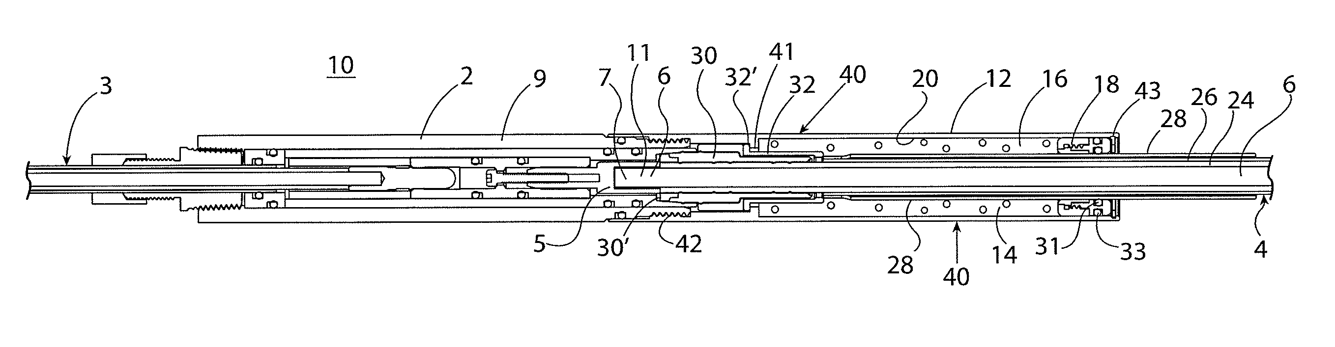
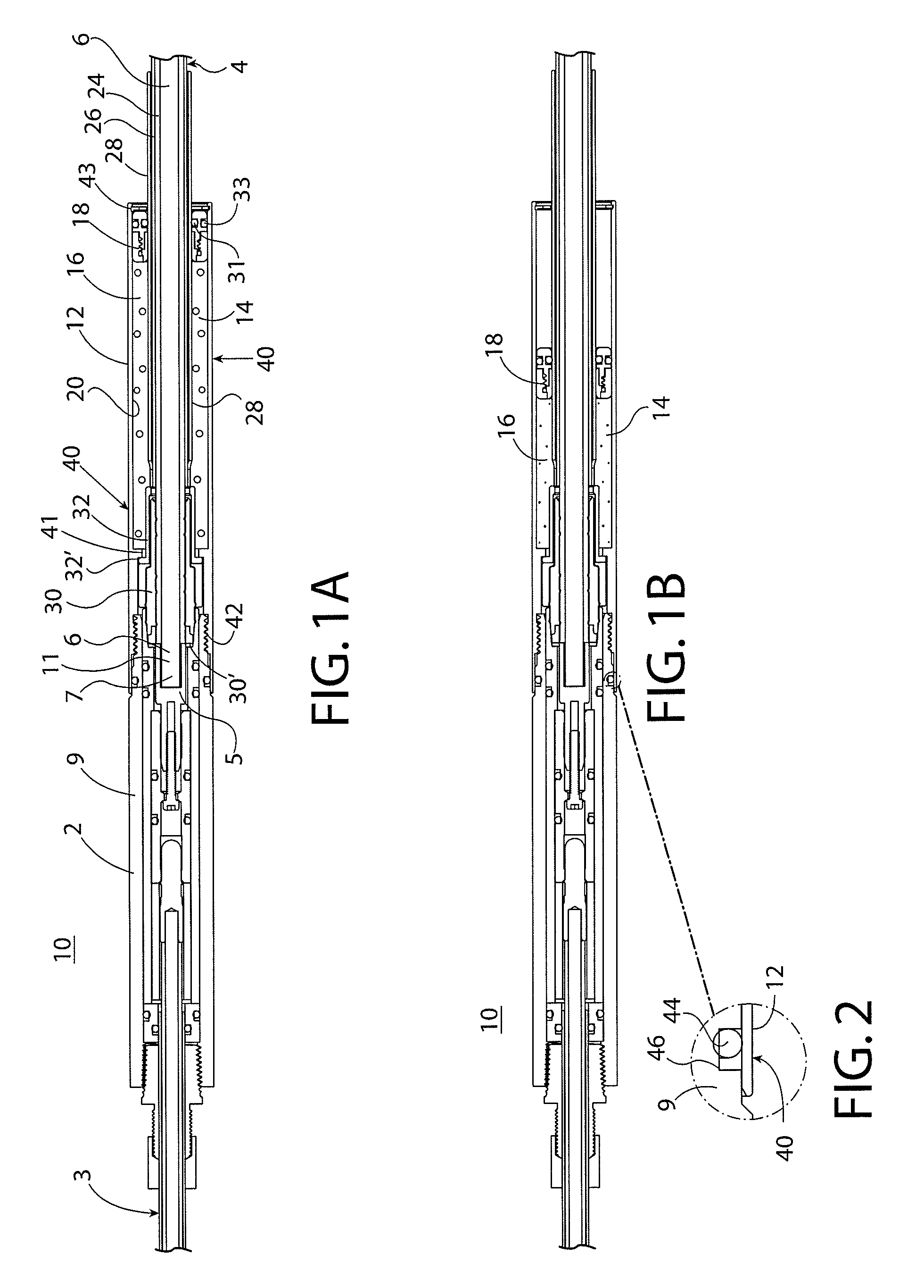
[0019]FIGS. 1A and 1B depict a cross-sectional view of a power cable assembly 10 according to one exemplary embodiment of the invention. In FIG. 1B, the power cable assembly 10 of FIG. 1A is shown exposed to external fluid pressure. The power cable assembly 10 generally includes a power cable sub-assembly 2 that is configured to be connected to a power cable 4 by a sleeve ass...


PUM

PropertyMeasurementUnit
pressureaaaaaaaaaa
flexibleaaaaaaaaaa
temperatureaaaaaaaaaa

Abstract

A pressure-balanced sleeve assembly for an electrical cable termination is disclosed. The sleeve assembly includes an outer sleeve surrounding the electrical cable; a chamber defined between the outer sleeve and the electrical cable; dielectric fluid contained within the chamber; and a seal that is positioned between the outer sleeve and the electrical cable to delimit and seal an end of the chamber to prevent the escapement of the dielectric fluid from the chamber, the seal being moveable along the cable in response to differences between a pressure within the chamber and a pressure outside of the chamber. Also disclosed herein is a pressure-balanced electrical cable assembly and a method of pressure-balancing a termination of an electrical cable.

Description

FIELD OF THE INVENTION[0001]This invention generally relates to a pressure-balanced electrical connector having a chamber filled with dielectric fluid.BACKGROUND OF THE INVENTION[0002]Power cables, which may be used for electric submersible pumps (ESP) in oil wells, are typically constructed with a copper conductor, an insulator that surrounds the copper conductor, and a lead sheath that surrounds the insulator. Lead-sheathed power cables are known and disclosed in, for example, U.S. Pat. No. 4,780,574 to Neuroth and U.S. Pat. No. 5,760,334 to Ziemek, each of which are incorporated by reference herein in their entirety.[0003]The lead material of the lead sheath protects the insulator of the power cable from damage resulting from the deleterious gases of the harsh oil well environment. The lead material of the lead sheath may also protect rubber sealing elements that are used to terminate these power cables. The rubber sealing elements are particularly vulnerable to explosive decompr...

Claims


Application Information

Patent Timeline
Patent Type & Authority Patents(United States)
IPC IPC(8): H01B7/18E21B33/04H01B13/22H01R13/52H01R13/523H02G15/04
CPCH01B7/1805H02G15/04H01R13/5205H01R13/523E21B33/04H01B13/221H01R13/5216Y10T29/49227
Inventor WILLIAMS, ROGER C.RUSH, BRADLEY DEAN
Owner ITT MFG ENTERPRISES LLC
Why Eureka
Try Eureka