Reflective optical scale for encoder and reflective optical encoder

a technology of reflective optical encoder and encoder, which is applied in the direction of optical elements, coatings, instruments, etc., can solve the problems of difficult to completely prevent the drop of reflectance light in these regions, and difficult to ensure the reflectance of light, so as to prevent the incorrect detection of light detectors and increase the contrast of images.

Inactive Publication Date: 2014-08-26
CANON KK
View PDF8 Cites 2 Cited by
  • Summary
  • Abstract
  • Description
  • Claims
  • Application Information

AI Technical Summary

Benefits of technology

[0007]The present invention provides a technique advantageous to prevent incorrect detection of a light detector by increasing the contrast of an image generated by reflected light from a scale.

Problems solved by technology

In the scale disclosed in Japanese Patent Laid-Open No. 2004-20283, since each concave portion is formed of a silicon substrate and each convex portion is formed on monocrystalline silicon, it is not easy to assure a reflectance of light as high as that detectable by the light detector in a wavelength range of light when an LED is used as the light source.
In the scale disclosed in Japanese Patent Laid-Open No. 2008-170286, since the metal films (reflecting regions) are also covered by the antireflection film, it is difficult to completely prevent a reflectance drop of light on these regions.

Method used


Image

  • Reflective optical scale for encoder and reflective optical encoder
  • Reflective optical scale for encoder and reflective optical encoder
  • Reflective optical scale for encoder and reflective optical encoder

Examples


first embodiment

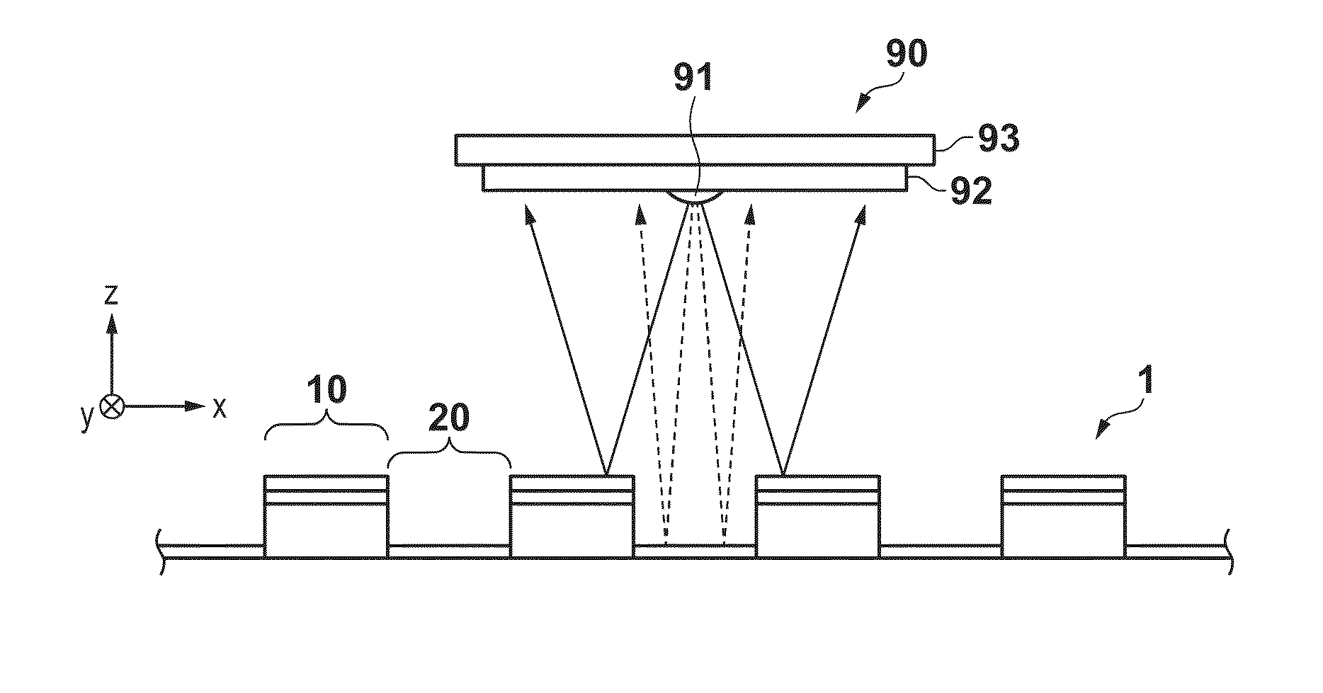
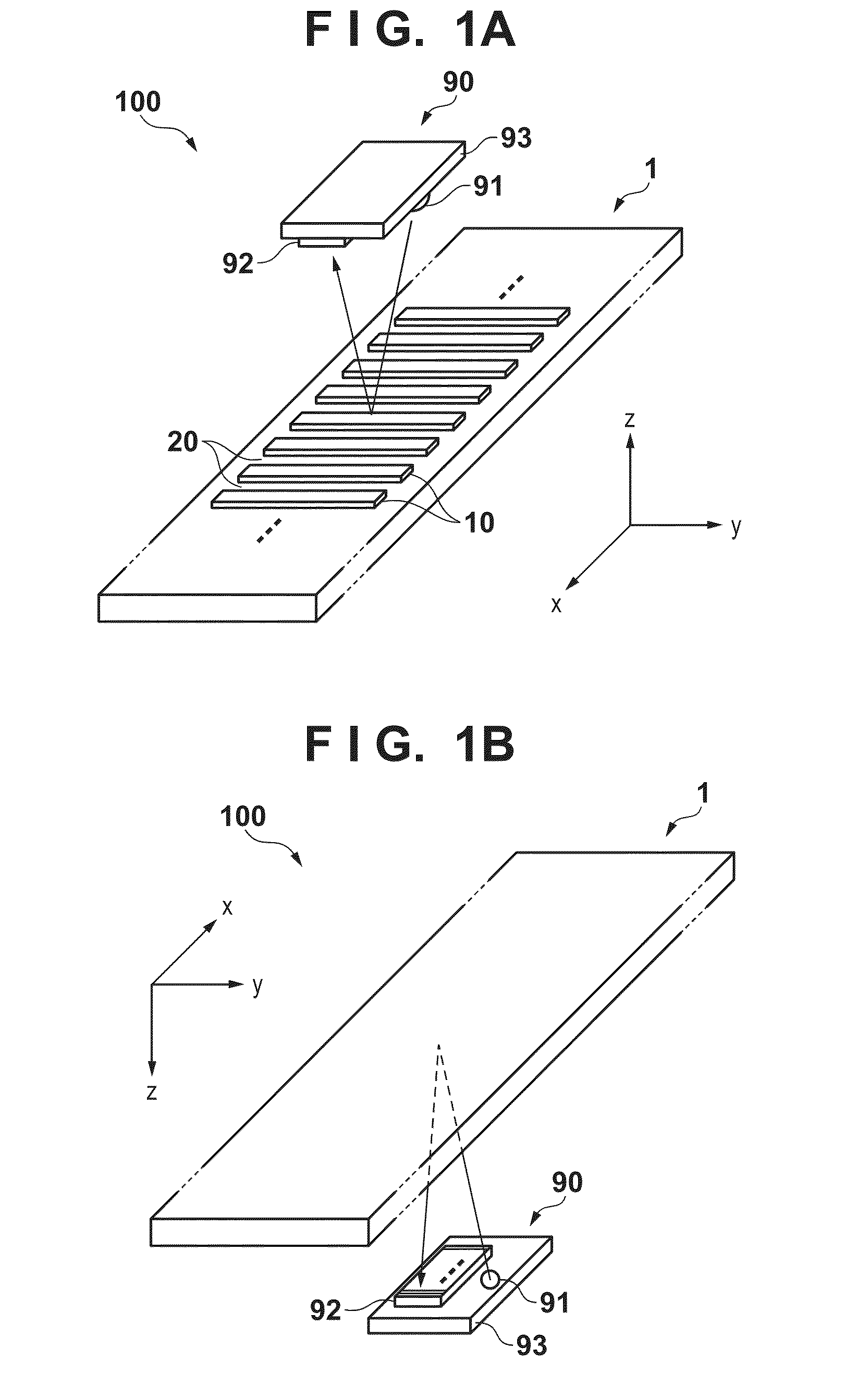
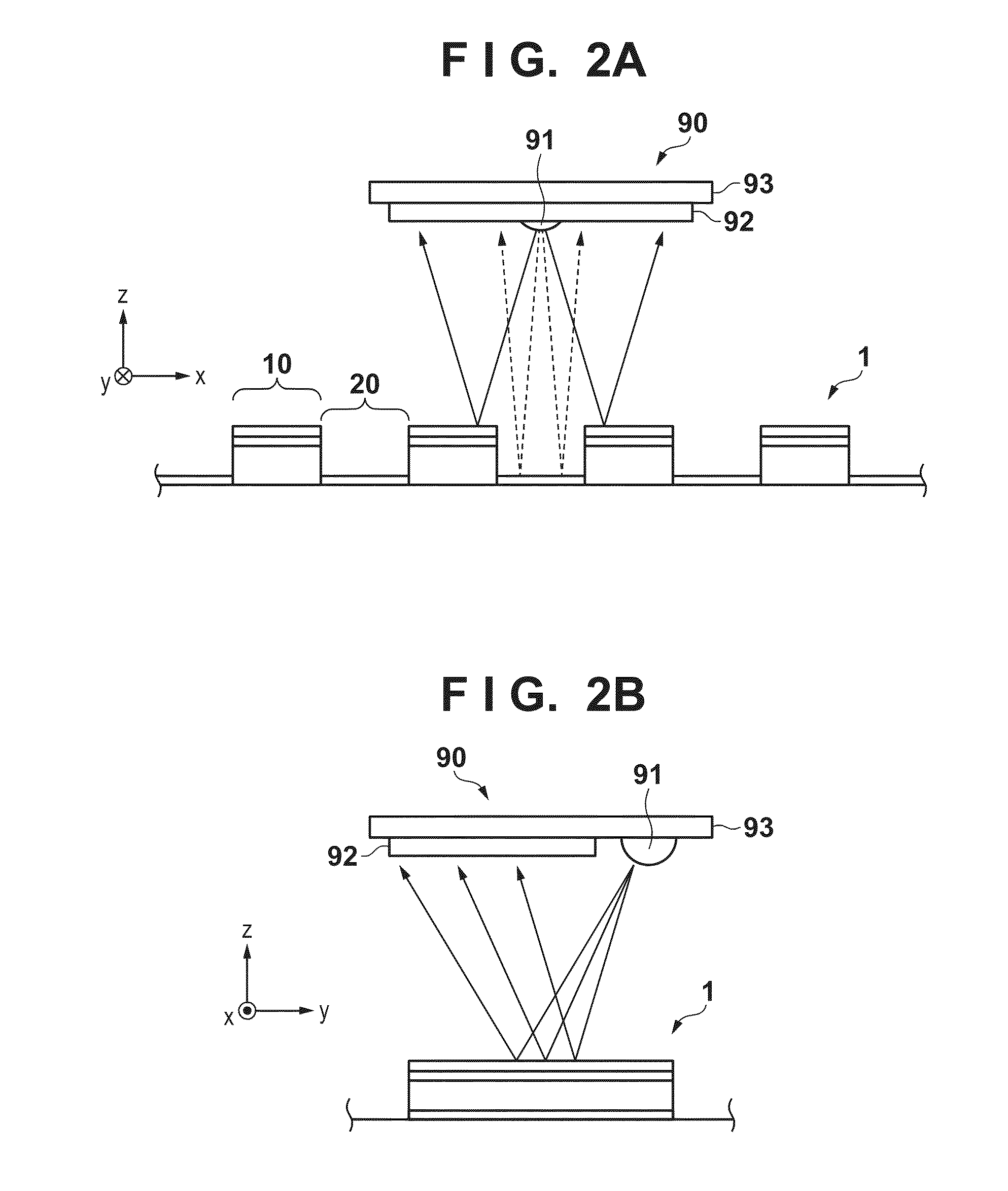
[0016]A reflective optical scale 1 for an encoder according to the first embodiment of the present invention will be described below with reference to FIGS. 1A to 6C. FIGS. 1A and 1B are schematic views for explaining a reflective optical encoder 100. The reflective optical encoder 100 includes a reflective optical scale 1 and detection head 90. The reflective optical scale 1 and detection head 90 can be arranged to oppose each other. In FIG. 1A, the reflective optical scale 1 is illustrated at a lower position, and the detection head 90 is illustrated at an upper position. In FIG. 1B, the reflective optical scale 1 is illustrated at an upper position, and the detection head 90 is illustrated at a lower position. The detection head 90 includes a light source 91, a light detector 92, and a detection substrate 93 including them. The light source 91 is, for example, a point light source LED which has a small light-emitting surface and can emit light of a single wavelength λ. In the fol...

second embodiment

[0027]As another example of the underlying member 30, a member prepared by forming a film including at least one of chromium, titanium, nickel, iron, and platinum on a substrate having light transparency may be used. In this case, it is required to form a metal film as thick as incoming light from the light source 91 is not transmitted. FIG. 3B shows a reflective optical scale 2 according to the second embodiment of the present invention. In this embodiment, as the underlying member 30, a member prepared by forming a metal film 80 of chromium on a glass substrate 70 was used. The metal film 80 of chromium was formed to have a thickness of 100 nm or more. Therefore, light emitted by the light source 91 is never transmitted through this metal film 80, and does not cause any incorrect operation of the encoder 100 or the like. A refractive index of light of the metal film 80 of chromium is about 4.31.

[0028]FIG. 6B is a table showing comparison results of the reflective optical scale 2 f...

third embodiment

[0031]When a member prepared by forming a metal film on a glass substrate or the like is used as another example of the underlying member 30 as in the second embodiment, for example, a material having a high refractive index such as nickel, iron, or platinum can also be selected as a material of the metal film. FIG. 3C shows a reflective optical scale 3 for an encoder according to the third embodiment of the present invention. In this embodiment, a member prepared by forming a metal film 81 of titanium on a glass substrate 70 was used as the underlying member 30. The metal film 81 of titanium was formed to have a thickness of 100 nm or more. Compared to the second embodiment in which the metal film of chromium is formed, the light transmittance can be suppressed to 0.1% or less. Therefore, light emitted by the light source 91 is never transmitted through this metal film 81, and does not cause any incorrect operation of the encoder 100 or the like. A refractive index of light of the ...


PUM

PropertyMeasurementUnit
thicknessaaaaaaaaaa
refractive indexaaaaaaaaaa

Abstract

A reflective optical scale for an encoder, in which a first region and a second region are alternately arranged on an underlying member, wherein the first region has a reflecting member on the underlying member, a layer made up of a first material, and a layer made up of a second material, the second region has the layer made up of the second material, the first and the second material have transparency, the first material has a lower refractive index of the light than the reflecting member and the second material, the second material has a lower refractive index of the light than the underlying member, and optical thicknesses of the first and the second material are set so that a reflectance of the light of the first region is higher than the second region.

Description

BACKGROUND OF THE INVENTION[0001]1. Field of the Invention[0002]The present invention relates to a reflective optical scale for an encoder and a reflective optical encoder.[0003]2. Description of the Related Art[0004]A reflective optical encoder used to obtain position information includes a reflective optical scale, a light source such as an LED which irradiates this scale with light, and a light detector which detects reflected light from this scale. On the reflective optical scale, reflecting regions and non-reflecting regions are alternately arranged, and the reflectance of light on the reflecting region is higher than that of light on the non-reflecting region. Thus, reflected light from the scale generates a fringe-like image (interference fringes) on the light detector arranged to oppose this scale. The light detector detects a phase shift of the fringes caused when the position of the scale moves in the length measurement direction. The reflective optical encoder processes d...

Claims


Application Information

Patent Timeline
Patent Type & Authority Patents(United States)
IPC IPC(8): G01D5/34G01D5/36G01D5/347G02B1/11G02B5/08
CPCG01D5/34707G02B1/11G02B5/0816
Inventor MIZUNO, HIROSHI
Owner CANON KK
Why Eureka
Try Eureka