
Method for the diagnostic testing of a mobile telephone terminal including contactless applications

a mobile telephone terminal and application technology, applied in the direction of transmission, wireless communication, telephonic communication, etc., can solve the problems of inability to access the service, the failure of contactless components, and the failure of the application

Inactive Publication Date: 2014-08-26
BOUYGUES TELECOM
View PDF18 Cites 5 Cited by
  • Summary
  • Abstract
  • Description
  • Claims
  • Application Information

AI Technical Summary

Benefits of technology

[0016]One aim of the invention is to allow rapid and simple identification of the causes of a malfunction.
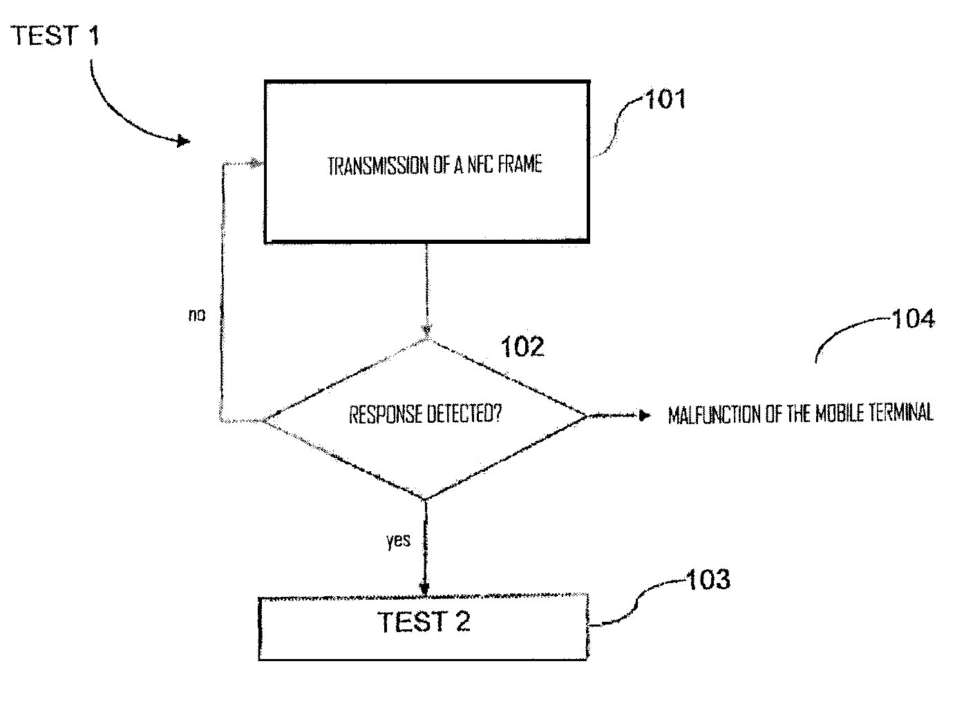
[0021]The UICC card is programmed with a specific test application allowing the mobile terminal to respond to the unit during a test operation. The test operation thus makes it possible to verify that the chain of contactless components (communication module and UICC card) is operating correctly, without having to remove the UICC card.
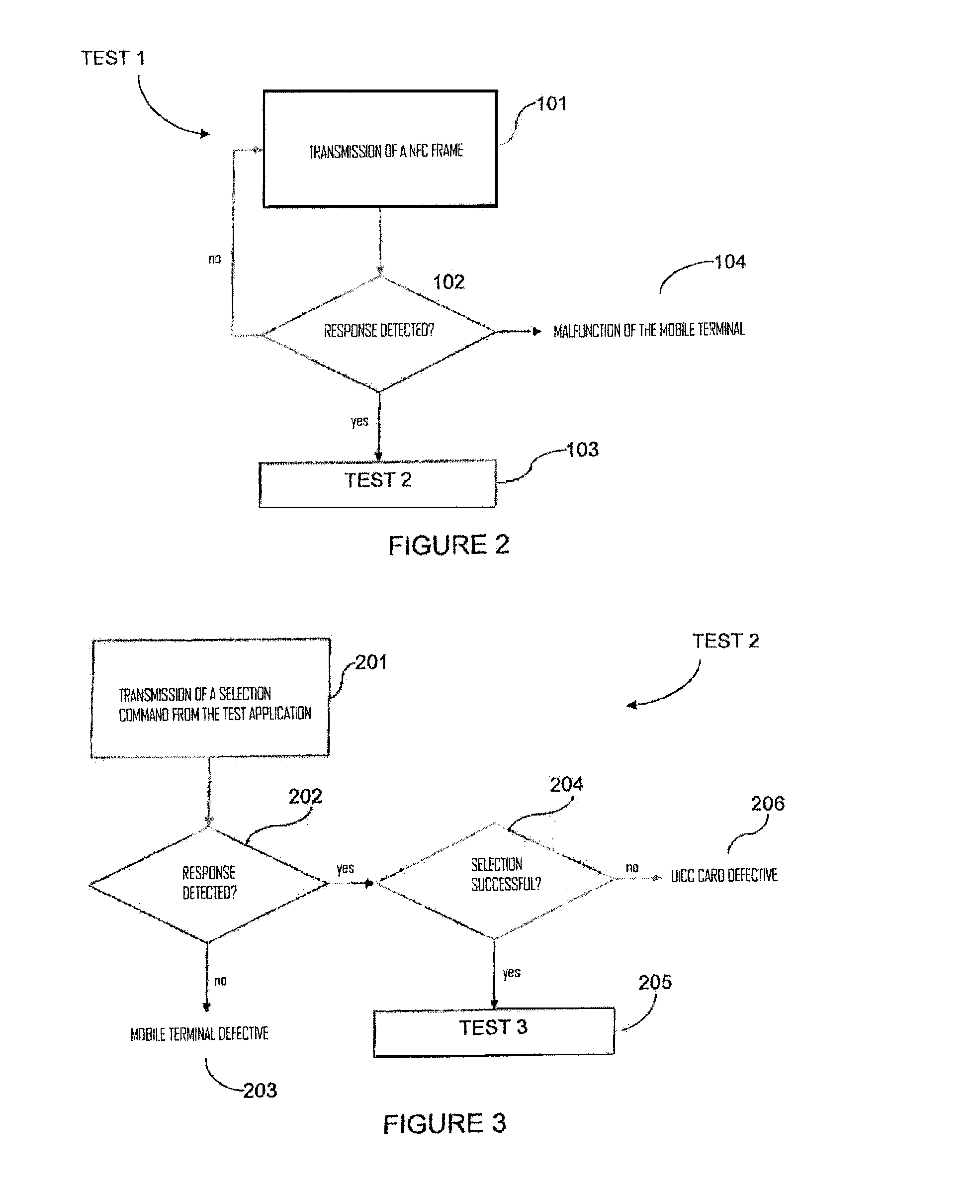
[0029]The prior test operation makes it possible to verify that the mobile terminal works before performing the test operation on the chain of contactless components.
[0038]The subsequent test operation is carried out in the case where both of the preceding test operations have not made it possible to conclude on a malfunction of the terminal or of the chain of contactless components. The subsequent test operation makes it possible to verify that a given contactless application is indeed present in the UICC card.

Problems solved by technology

However, the problems encountered may have different causes:
In a first case, the inability to access the service may result from a malfunction of the contactless components of the mobile telephone or the UICC card containing the stored application.
In a second case, the inability to access the service may result from a malfunction in the application.
However, it is sometimes difficult to identify the causes of the malfunctions to orient the user towards the appropriate representative (the mobile telephone operator or the service supplier).
Moreover, it is not currently possible to test the other components of the mobile terminal.

Method used


Image

  • Method for the diagnostic testing of a mobile telephone terminal including contactless applications
  • Method for the diagnostic testing of a mobile telephone terminal including contactless applications
  • Method for the diagnostic testing of a mobile telephone terminal including contactless applications

Examples


Embodiment Construction

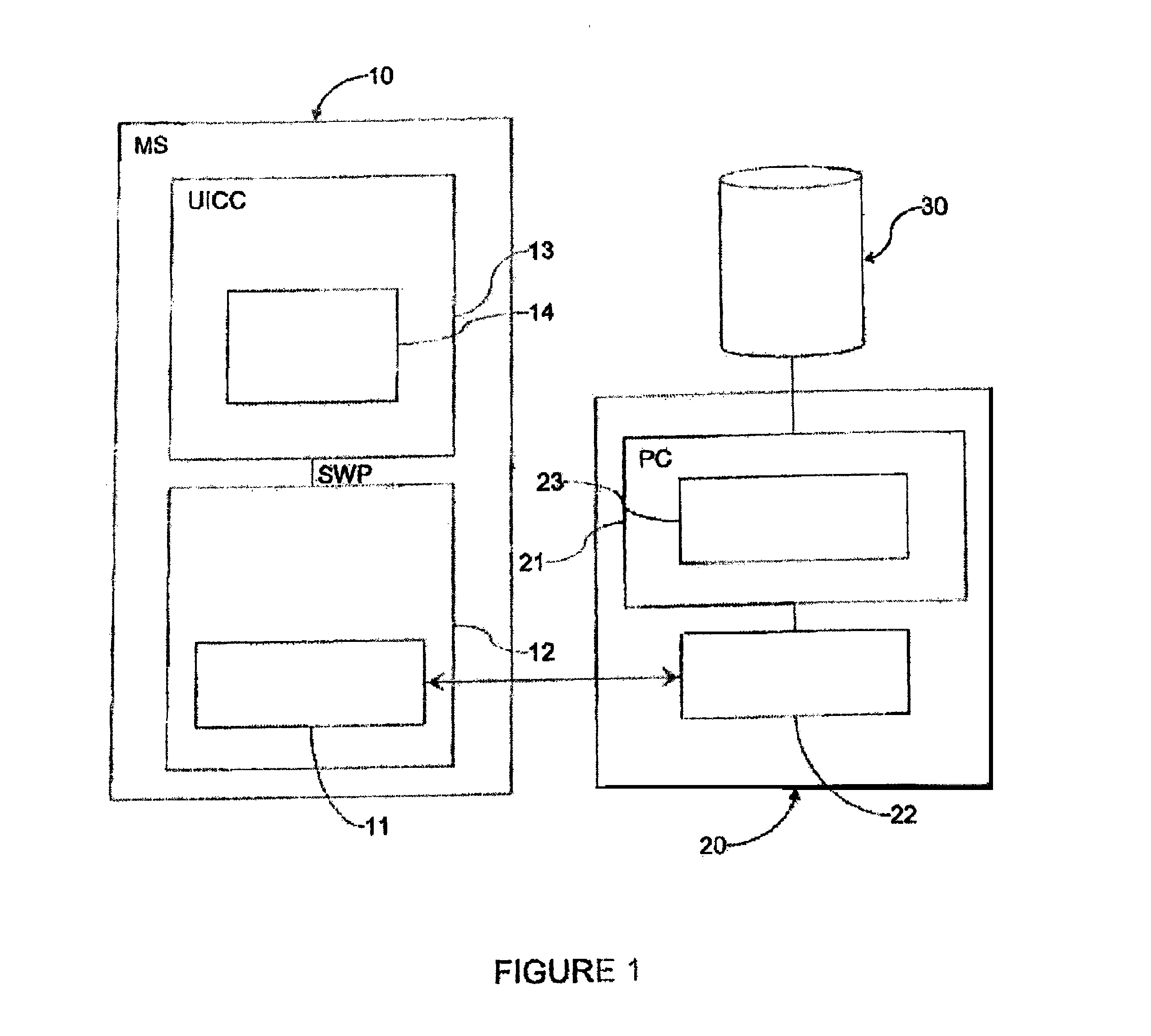
[0049]FIG. 1 diagrammatically shows a mobile telephone terminal 10 and a diagnostic unit 20.

[0050]The mobile telephone terminal 10 is a terminal able to establish telephone communications via a mobile telephone cellular network.

[0051]The mobile telephone terminal 10 is also adapted to exchange data with a contactless unit.

[0052]To that end, the terminal 10 comprises a contactless communication module 12 including a specific antenna 11, and a UICC card 13 in which one or several contactless applications are stored. The UICC card 13, which is for example a SIM card, in particular contains a test application 14.

[0053]The UICC card 13 is initially programmed with the test operation 14 during manufacture in the plant or is configured remotely. In the latter case, the application 14 is sent to the mobile terminal via the cellular telephone network (OTA—Over the Air—transmission) and is stored in the UICC card.

[0054]Traditionally, the communication module 12 is connected to the UICC card 1...


PUM


Abstract

The invention relates to a method for the diagnostic testing of a mobile telephone terminal (10) including: a UICC card (13) containing a stored test application, and a contactless communication module (12) which can exchange data with a contactless unit (20) by retromodulation of a signal transmitted by the unit, said method comprising a test operation whereby the unit: emits a test application selection request; detects a response indicating application selection confirmation or failure, transmitted by the mobile telephone terminal; and determines the operating state of the UICC card or of the terminal as a function of the response detected.

Description

[0001]This is a non-provisional application claiming the benefit of International application number PCT / EP2009 / 054953 filed Apr. 24, 2009.FIELD OF INVENTION[0002]The invention concerns a method for the diagnostic testing of a mobile telephone terminal including one or several contactless applications. The invention also concerns an associated contactless unit, and an associated mobile telephone terminal.BACKGROUND OF THE INVENTION[0003]More and more services use wireless communication techniques. These techniques allow devices to exchange data with each other or with a contactless chip card, via a short range radiofrequency connection (typically in the vicinity of a few centimeters in the framework of the ISO 14443 standard) or a proximity radiofrequency connection (in the vicinity of a meter in the framework of the ISO 15693 standard).[0004]“Contactless” describes an exchange of data between a contactless reader (Proximity Coupling Device—PCD) and a contactless card (Proximity Int...

Claims


Application Information

Patent Timeline
Patent Type & Authority Patents(United States)
IPC IPC(8): H04W24/00H04B1/38
CPCH04L12/2697H04L43/50H04W24/06
Inventor JACOB, ANTOINEGRONDIN, CHARLES-EMILELE PALLEC, PIERRE
Owner BOUYGUES TELECOM
Learn More