Device for loading and unloading a freeze drying system

a technology for freezing drying and devices, which is applied in drying, cranes, light and heating equipment, etc., can solve the problems of troublesome cleaning, inability to retrofit a freeze drying installation which is to be loaded and/or unloaded manually to allow an integrated automated process, and in any case render the front of a freeze drying installation more difficult, so as to achieve easy maintenance and cleaning work

Active Publication Date: 2014-09-02
MARTIN CHRIST GEFRIERTROCKNUNGSANLAGEN
View PDF14 Cites 7 Cited by
  • Summary
  • Abstract
  • Description
  • Claims
  • Application Information

AI Technical Summary

Benefits of technology

[0010]It is the object of the invention to create a device of the type presented in the introduction in such a way that, in addition to a mechanically simple construction which can also be retrofitted without considerable outlay to chambers prepared in accordance with the invention, in particular aspects of asepsis are considered so that maintenance and cleaning wor...

Problems solved by technology

Retrofitting of a freeze drying installation which is to be loaded and/or unloaded manually to allow an integrated automated process is currently not possible or is possible only with considerable outlay.
Separate systems for both loading and unloading are provided which are formed in mechanically entirely different ways and which are each of a relatively complicated construction and are therefore formed such that in association therewith they are prone to collecting dirt so that they are consequently troublesome to clean.
In particular, the achievement of a condition which is sufficiently aseptic for use in, and in front of, a freeze drying installation is in any case rendered more difficult.
The results of this are also found, amongst other places, in the said linkage systems which, in the same manner as the carriage, are guided in a plane above the standing surface to be unloaded, so that at this location abrasion is unavoidably produced wh...

Method used


Image

  • Device for loading and unloading a freeze drying system
  • Device for loading and unloading a freeze drying system
  • Device for loading and unloading a freeze drying system

Examples


Embodiment Construction

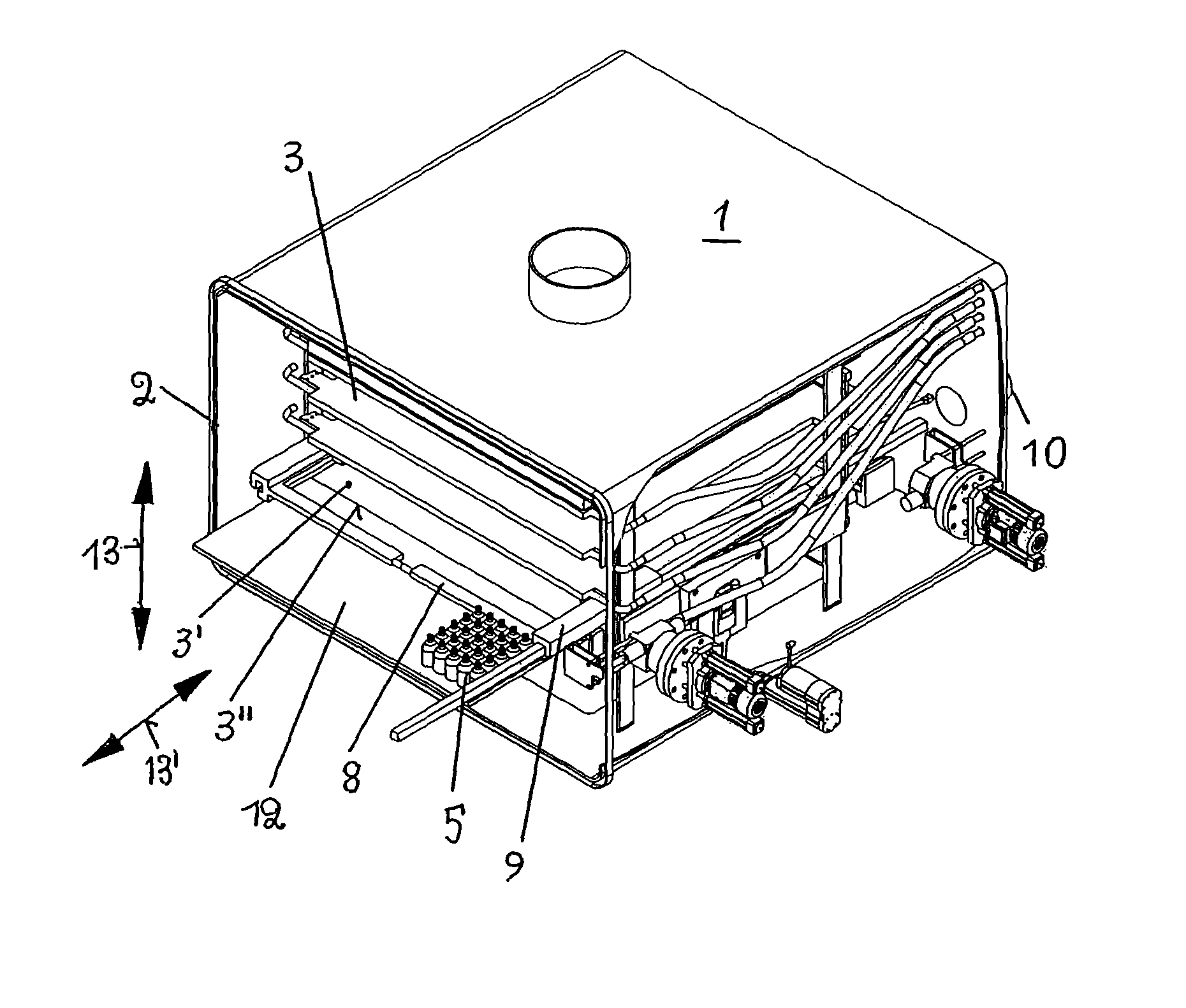
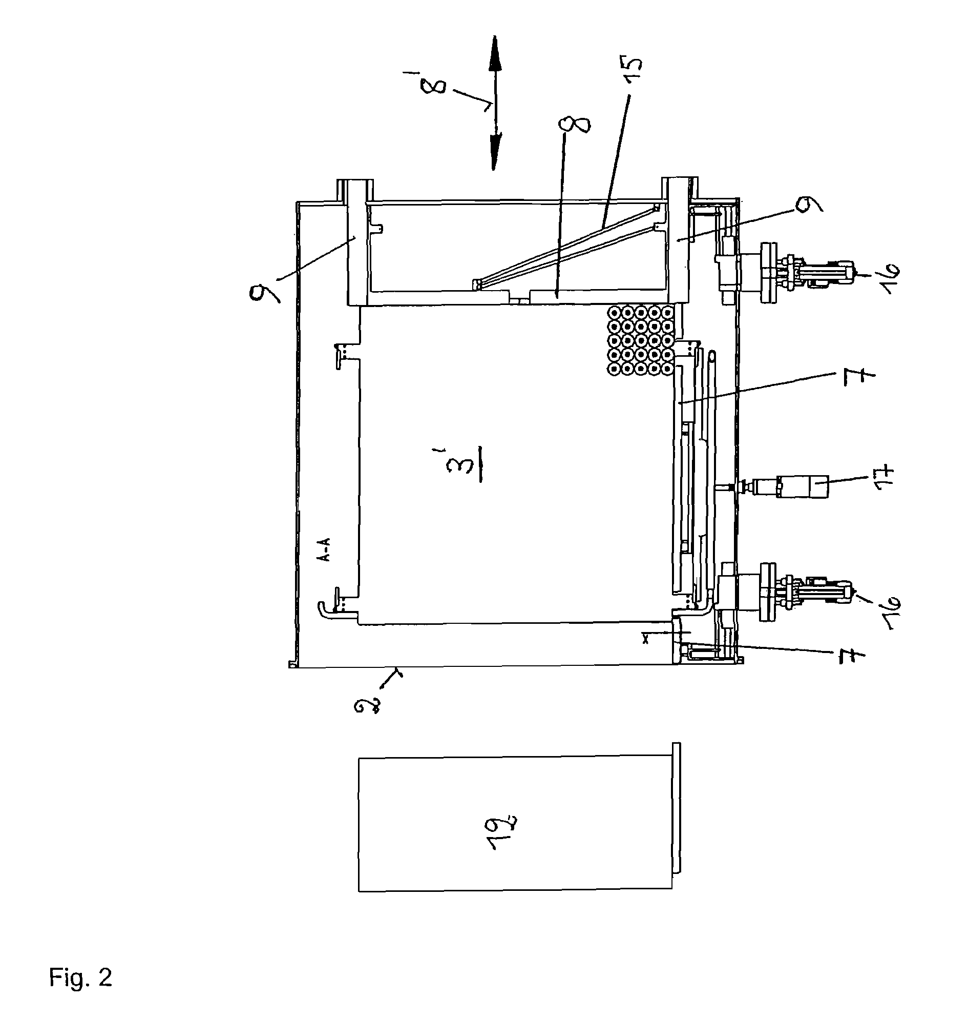
[0041]FIG. 1 shows a cross-sectional view of the drying chamber 1 of a freeze drying installation, located in the front side 2 of which is a closable orifice, not shown in the drawing, for loading or unloading drying vessels 5. The drying chamber 1 is connected to a condenser chamber in a manner which is known per se, however, no further detail will be given thereof at this point.

[0042]Within the drying chamber 1 is located an arrangement of standing surfaces 3 which are held in a vertically movable manner in a frame 4 in a manner known per se. These standing surfaces 3 serve for drying vessels 5, each containing a substance to be dried, to stand on, which drying vessels are to be removed from the drying chamber 1 after the drying process is concluded. The number 6 designates a height position, in this case the standing surface 3′ which corresponds to the unloading position of this standing surface. It is significant that the vertical displaceability of all standing surfaces 3 of th...


PUM


Abstract

A device for loading and unloading the standing surface of the drying chamber of a freeze drying installation. The device includes a carriage disposed above an unloading position of the surface which extends transversely to a movement direction during a loading or unloading process and in parallel with the standing surface and forms a movable guiding edge for the drying vessels. Guides disposed on both sides of the standing surface extend in parallel with the movement direction and form fixed guiding edges for the drying vessels. The carriage is driven by two linear motors, the respective primary parts of which are fixedly connected to both side ends of the carriage and are supported on the guides which at the same time receive the secondary parts. All of the components of the devices thus defined are located within the drying chamber, wherein a mechanically extremely simple and low-wear construction is achieved.

Description

CROSS REFERENCE TO RELATED APPLICATIONS[0001]This application is the U.S. National Phase application of PCT International Application No. PCT / EP2010 / 006180, filed Oct. 11, 2010, which claims priority to German Patent Application No. 10 2009 049 142.2, filed Oct. 12, 2009.FIELD OF THE INVENTION[0002]The invention relates to loading and / or unloading devices for a freeze drying installation for pushing drying vessels, which contain a material to be dried and stand on one of the plurality of standing surfaces of the drying chamber of the freeze drying installation, in a movement direction for the purpose of unloading or loading the standing surface through at least one opening in the wall of the drying chamber, having a carriage which forms a guiding edge, moveable in the movement direction, and is intended to exert an advancing effect on the drying vessels, which carriage is displaceably supported on guides which are disposed inside the drying chamber on both sides at a distance from t...

Claims


Application Information

Patent Timeline
IPC IPC(8): B65G25/08B65G47/66F26B5/06F26B25/00
CPCF26B5/06F26B25/001
Inventor CHRIST, MARTIN
Owner MARTIN CHRIST GEFRIERTROCKNUNGSANLAGEN
Why Eureka
Try Eureka