Zoom lens and imaging apparatus

a zoom lens and imaging apparatus technology, applied in the field of zoom lenses and imaging apparatuses, can solve the problems of difficult to be regarded as a wide angle, disadvantageous lenses, and size reduction of patent documents 1 and 2, and achieve the effects of reducing size, widening angle of view, and reducing cos

Inactive Publication Date: 2014-09-02
FUJIFILM CORP
View PDF12 Cites 7 Cited by
  • Summary
  • Abstract
  • Description
  • Claims
  • Application Information

AI Technical Summary

Benefits of technology

[0007]In recent years, with respect to zoom lenses in the aforementioned fields, there is a request for structuring a lens in such a manner to have a wide angle of view while a high magnification ratio of, for example, about 5 times is secured. Further, there is a request for structuring the lens in such a manner that reduction in the size of an imaging apparatus is possible when the lens is mounted on the imaging apparatus, and reduction in cost is also requested. However, in the zoom lens disclosed in Patent Document 1, a first lens group, which is a most object side group including a large outer diameter lens, is a moving group. Therefore, a drive system for moving the lens group becomes large. Hence, Patent Document 1 is disadvantageous to reduction in size and in cost. In the zoom lens disclosed in Patent Document 2, a full angle of view at a wide angle end is about 82 degrees, which is wide. However, a most-object-side lens having a large outer diameter is an aspherical lens having a high refractive index. Therefore, the lens is disadvantageous when a cost is an important factor. The zoom lens disclosed in Patent Document 3 has a variable magnification ratio of about 5 times. However, a full angle of view at a wide angle end is about 65 degrees, which is hard to be regarded as a wide angle. In the zoom lens disclosed in Patent Document 4, a variable magnification ratio is about 6.7 times, and a full angle of view at a wide angle end is about 80 degrees. However, the total length is long, and the number of lenses constituting the zoom lens is large. Therefore, an improvement is needed in reduction in size and in cost.
[0008]In view of the foregoing circumstances, it is an object of the present invention to provide a zoom lens the size of which is reduced, and the angle of view of which is widened, and which can be structured at a low cost, while excellent optical performance and a high magnification ratio are secured. Further, it is another object of the present invention to provide an imaging apparatus including the zoom lens.
[0017]The first zoom lens of the present invention is a zoom lens of at least five lens groups. Five lens groups the refractive powers of which are positive, negative, positive, positive, and negative are arranged in this order from the object side, and the second lens group, the fourth lens group and the fifth lens group are moved during changing magnification. In the zoom lens, the first lens group is always fixed during changing magnification and during focusing, and the lens structure is appropriately set, and especially the second lens consists of four lenses, the arrangement of the powers of which is optimized. Therefore, it is possible to easily reduce a size, widen an angle of view, and reduce a cost while an excellent optical performance and a high magnification ratio are secured.
[0028]The second zoom lens of the present invention is a zoom lens of at least five lens groups. Five lens groups the refractive powers of which are positive, negative, positive, positive, and negative are arranged in this order from the object side, and the second lens group, the fourth lens group and the fifth lens group are moved during changing magnification. In the zoom lens, the first lens group is always fixed during changing magnification and during focusing, and the lens structure is appropriately set, and especially the refractive power of the second lens is optimized in such a manner to satisfy formula (2A). Therefore, it is possible to easily reduce a size, widen an angle of view, and reduce a cost while an excellent optical performance and a high magnification ratio are secured.
[0050]According to the zoom lens of the present invention, the lens structure of a zoom lens of at least five group type is appropriately set, and especially, the structure of the second lens group is optimized. Therefore, it is possible to reduce a size, widen an angle of view, and reduce a cost while an excellent optical performance and a high magnification ratio are secured.
[0051]According to the imaging apparatus of the present invention, the apparatus includes the zoom lens of the present invention. Therefore, imaging at a wide angle of view is possible, and it is possible to reduce a size and a cost while a high imaging performance including an excellent optical performance and a high magnification ratio is secured.

Problems solved by technology

Hence, Patent Document 1 is disadvantageous to reduction in size and in cost.
Therefore, the lens is disadvantageous when a cost is an important factor.
The zoom lens disclosed in Patent Document 3 has a variable magnification ratio of about 5 times. However, a full angle of view at a wide angle end is about 65 degrees, which is hard to be regarded as a wide angle.
However, the total length is long, and the number of lenses constituting the zoom lens is large.

Method used


Image

  • Zoom lens and imaging apparatus
  • Zoom lens and imaging apparatus
  • Zoom lens and imaging apparatus

Examples


Embodiment Construction

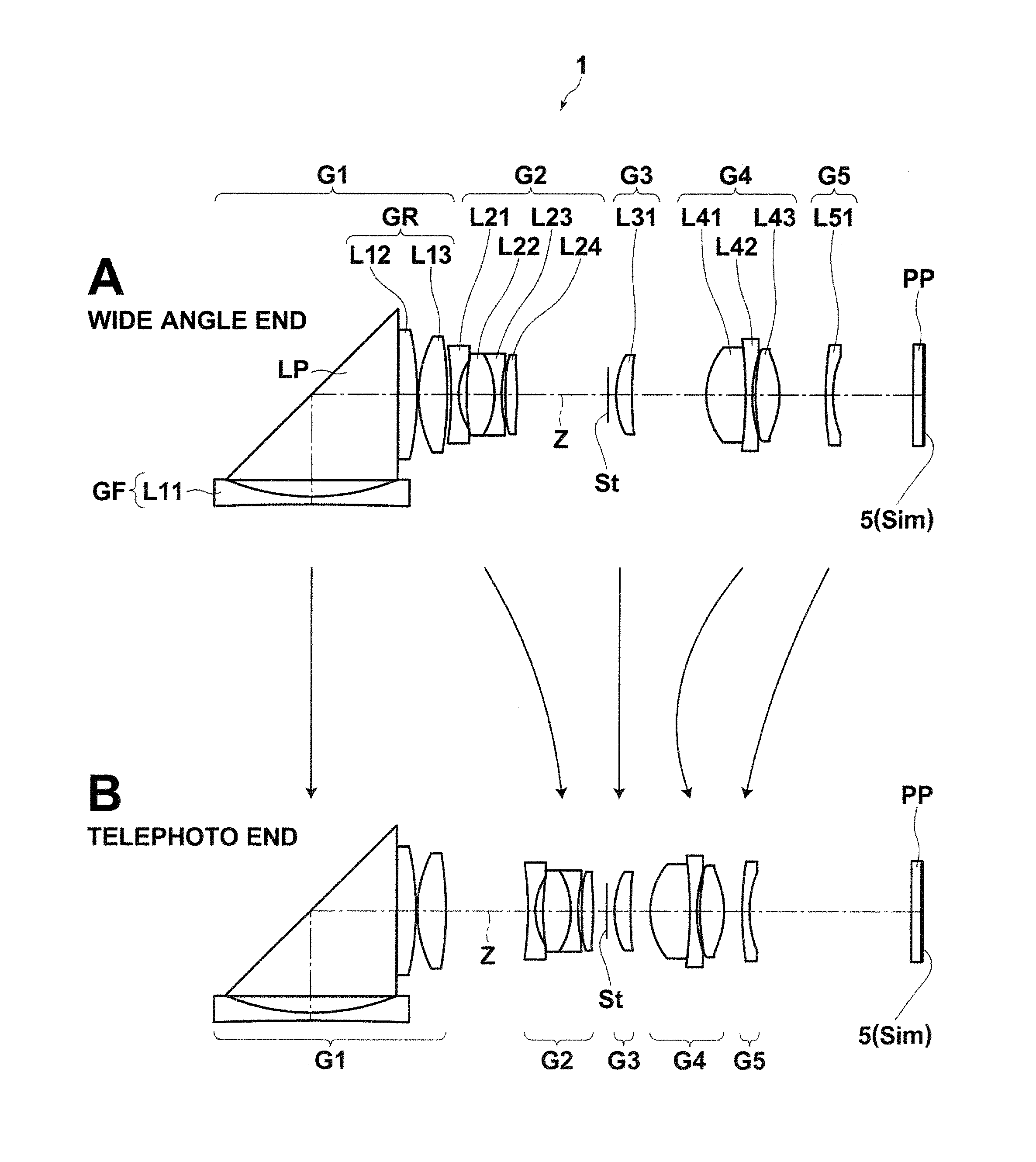
[0068]Hereinafter, embodiments of the present invention will be described in detail with reference to drawings. First, a zoom lens according to an embodiment of the present invention will be described with reference to FIG. 1, Sections A and B.

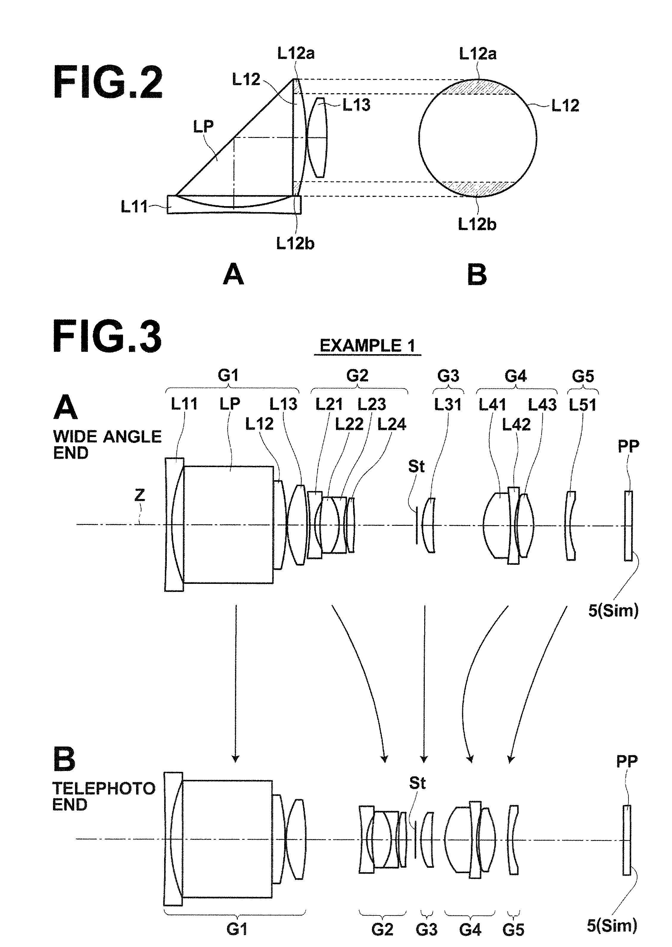
[0069]FIG. 1, Section A and FIG. 1, Section B are cross sections of a structure example of a zoom lens 1 according to an embodiment of the present invention. The structure example illustrated in FIG. 1, Section A and FIG. 1, Section B correspond to a zoom lens in Example 1, which will be described later. FIG. 1, Section A and FIG. 1, Section B illustrate the arrangement of lenses at a wide angle end and at a telephoto end, respectively, in a state of focusing on an object at infinity. Further, arrows between FIG. 1, Section A and FIG. 1, Section B schematically illustrate the path of movement of each lens group when magnification is changed.

[0070]The zoom lens 1 includes five lens groups of first lens group G1 through fifth lens group G5. The ...


PUM


Abstract

A zoom lens includes a positive first lens group, which is fixed during changing magnification and during focusing, a negative second lens group, which is moved during changing magnification, a positive third lens group, which is fixed during changing magnification and during focusing, a positive fourth lens group, which is moved during changing magnification and during focusing, and a negative fifth lens group, which is moved during changing magnification, which are in this order from an object side. A lens group constituting the first lens group consists of a negative front group and a positive rear group in this order from the object side. The second lens group consists of four lenses of a negative lens, a positive lens, a negative lens, and a positive lens or a negative lens arranged in this order from the object side.

Description

CROSS REFERENCE TO RELATED APPLICATIONS[0001]This application is a continuation of PCT / JP2011 / 006824 filed on Dec. 6, 2011, which claims foreign priority to Japanese Application No. 2010-272144 filed on Dec. 7, 2010. The entire contents of each of the above applications are hereby incorporated by reference.BACKGROUND OF THE INVENTION[0002]1. Field of the Invention[0003]The present invention relates to a zoom lens and an imaging apparatus. In particular, the present invention relates to a zoom lens appropriate for a digital camera, a video camera or the like using an imaging device, such as a CCD (Charge Coupled Device) and a CMOS (Complementary Metal Oxide Semiconductor), and an imaging apparatus including the zoom lens.[0004]2. Description of the Related Art[0005]In recent years, as personal computers spread to ordinary families, digital cameras that can input image information, such as a landscape and a portrait, obtained by photography to personal computers became widely used. As...

Claims


Application Information

Patent Timeline
Patent Type & Authority Patents(United States)
IPC IPC(8): G02B15/14
CPCG02B15/14G02B15/173G02B15/145113
Inventor TOMIOKA, RYOKO
Owner FUJIFILM CORP
Why Eureka
Try Eureka