
Mobile communication device with electromagnetic radiation sensors

a mobile communication device and electromagnetic radiation technology, applied in the field of wireless communication devices, can solve the problems of affecting the operation of electronic equipment, affecting the quality of life of people subjected to strong electromagnetic radiation, and affecting the quality of life of people, so as to achieve the effect of improving the quality of life, reducing the risk of serious diseases, and improving the safety of people's health

Inactive Publication Date: 2014-09-02
PATENT ARMORY INC
View PDF12 Cites 47 Cited by
  • Summary
  • Abstract
  • Description
  • Claims
  • Application Information

AI Technical Summary

Benefits of technology

The patent describes a mobile communication device that can detect and measure different types of electromagnetic radiation. The device uses different sensors for detecting pollution in different ranges. When the device detects a certain level of electromagnetic radiation, it will alert the user. The device also has a camera that can capture images and help the user aim the thermal radiation sensor. The captured images can be used as a viewfinder for the device. The technical effect of this patent is to provide a mobile communication device with the ability to detect and measure different types of electromagnetic radiation, and to help the user aim the thermal radiation sensor.

Problems solved by technology

These EMF create the so-called low and radio-frequency EMF pollution that may have negative effects on humans and interfere with electronic equipment.
Humans subjected to strong EMF may have increased risk of developing serious diseases, such as cancer, loss of reproductive functions, etc.
Electronic equipment subjected to the interfering EMF may malfunction.
However, the cost and complexity of incorporating a proximity sensor in a mobile communication device together with inability of the proximity sensor to determine the correct position of the IR sensor make it desirable to find an alternative solution.

Method used


Image

  • Mobile communication device with electromagnetic radiation sensors
  • Mobile communication device with electromagnetic radiation sensors
  • Mobile communication device with electromagnetic radiation sensors

Examples


Embodiment Construction

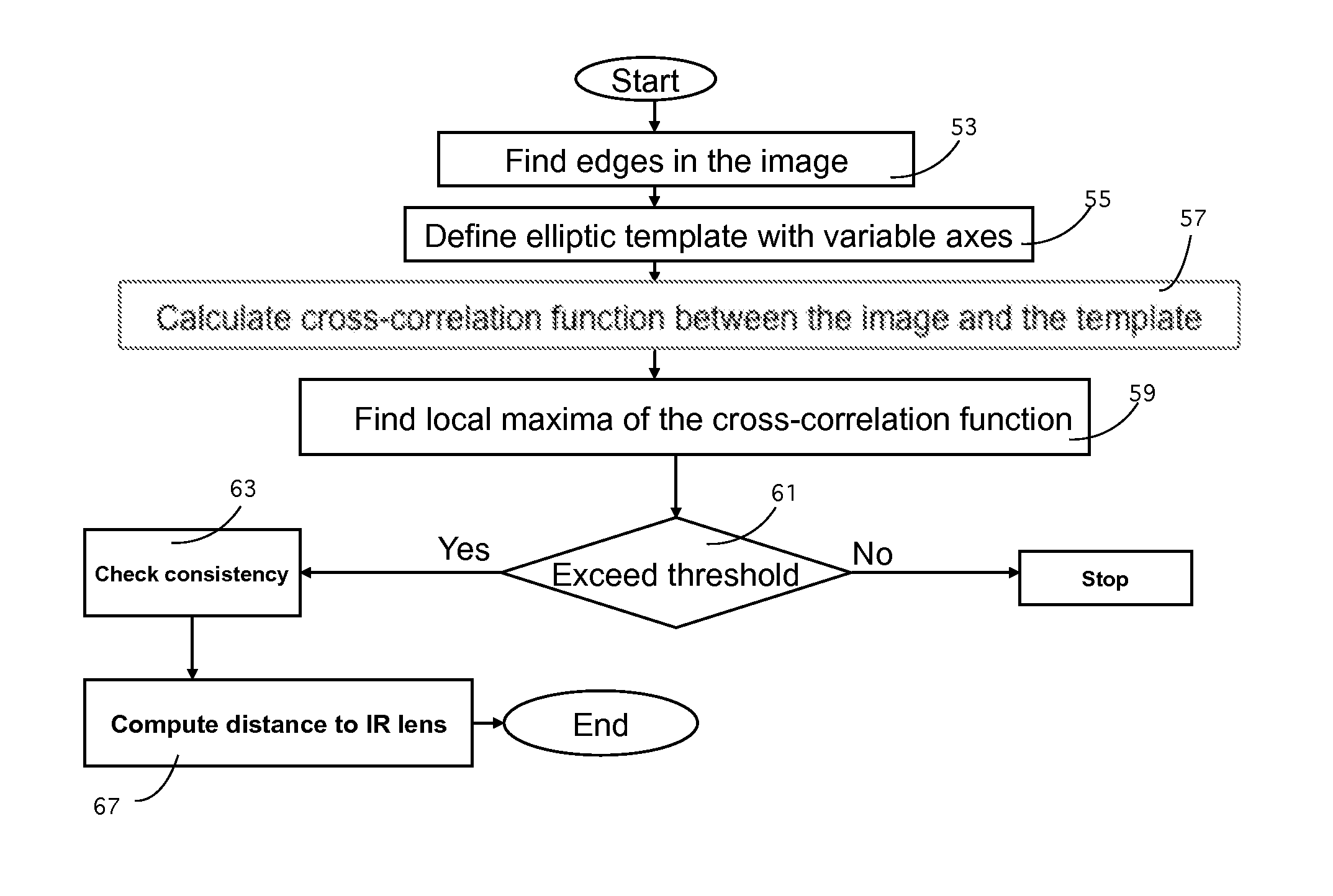
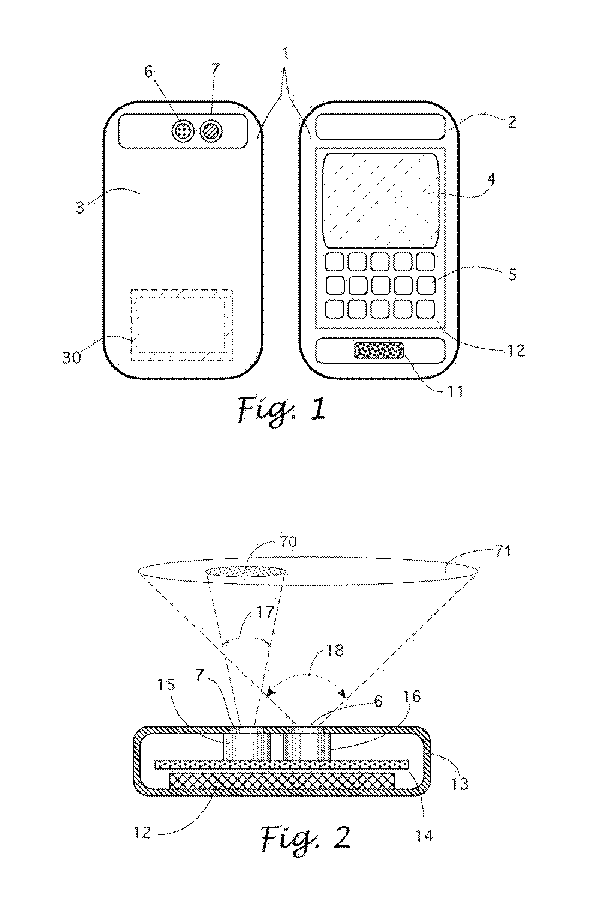
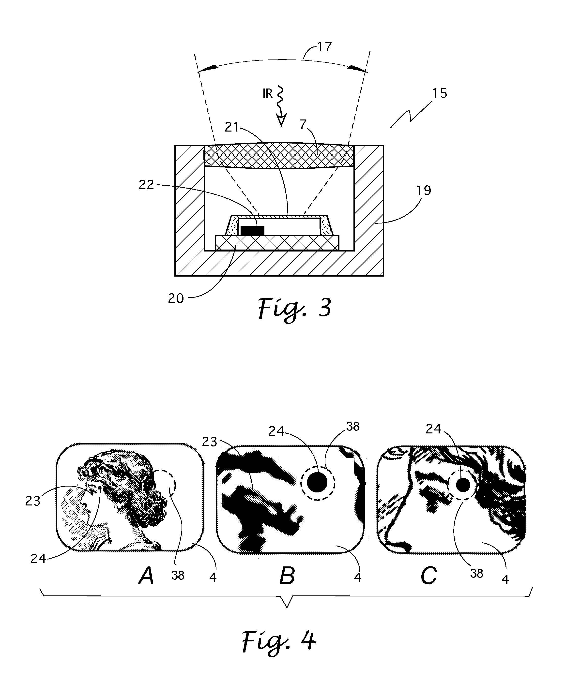
[0031]The central problem in non-contact temperature measurement is finding a location on the surface of the subject or object that is best suited for such measurement that is free from various obstructions and occlusions such as clothing, hair, decorations, etc. Furthermore, due to limitations of the optical components, the non-contact IR sensor should be positioned within a specific range of distances from the surface of the object where temperatures are measured. On the human face, these locations include the area of the temple within about 1 cm of the corner of the eye and the area of the forehead above the root of the nose between the eyes. The optimal range of distances between the surface of the skin and the IR sensor is between 2 and 10 cm. The present invention utilizes the imaging capabilities of a camera-equipped communication device to assist in accurate positioning of the sensor embedded into the communication device. The invention provides the device's operator with a ...


PUM


Abstract

A hand-held mobile communication device, such as smart telephone, alone or in protective case, incorporating sensors and signal conditioning modules for measuring signals from external sources of electromagnetic radiation (EMR) in different spectral ranges. These include detector monitoring EMR that pose potential health hazards or may interfere with various electronic devices. Other integrated EMR sensor is a photodiode for the ultraviolet detection to monitor the user's sun exposure and a thermal infrared detector for non-contact measurement of temperature of humans or inanimate objects. This detector in combination with a digital camera and a pattern recognition signal processing allows accurate non-contact measuring temperatures at specific location.

Description

[0001]This application is a continuation of the non-provisional U.S. patent application Ser. No. 13 / 303,054 filed on 22 Nov., 2011, now U.S. Pat. No. 8,275,413, that claims the priority of provisional U.S. patent application Ser. No. 61 / 627,070 filed on 17 Sep., 2011, and the currently pending PCT patent application No. PCT / US12 / 51676 filed on 21 Aug. 2012.[0002]The disclosures of the prior related applications and the U.S. patent are fully incorporated by reference herein.BACKGROUND OF THE INVENTION[0003]a. Field of the Invention[0004]The present invention relates generally to wireless communication devices. More specifically, this invention relates to mobile communication devices that incorporate additional sensors and detectors.[0005]b. Description of Prior Art[0006]Most wireless communication devices (cellular or mobile telephones, e.g.) incorporate additional non-communication features, such as imaging (photo and video), personal planners, games, etc. There are numerous inventi...

Claims


Application Information

Patent Timeline
IPC IPC(8): H04M1/02H04W88/02H04M1/00
CPCH04M1/72522H04M2250/12H04M1/0264H04N5/33H04N3/09H04W88/02H04B1/3838H04M2250/52G01J1/429G01J5/0265G01J5/0806G01J5/089G01J5/10G01J2001/4266H04M1/72403G01J5/07
Inventor FRADEN, JACOBPINTSOV, DAVID A.
Owner PATENT ARMORY INC
Learn More