Relocation detection method and relocation detection unit

a detection method and a technology for detecting units, applied in the direction of burglar alarms, mechanical actuation of burglar alarms, and the removal of hand-held items, etc., can solve the problems of difficult to prohibit the relocation of the apparatus, the sensitivity of the sensor cannot be increased, and the difficulty of avoiding erroneous detection caused, etc., to achieve the effect of vibration generated during the operation

Inactive Publication Date: 2014-09-02
DMG MORI CO LTD
View PDF14 Cites 1 Cited by
  • Summary
  • Abstract
  • Description
  • Claims
  • Application Information

AI Technical Summary

Benefits of technology

[0008]The original purpose of the relocation detection is to prevent the apparatus with high accuracy and / or high function from being used to develop weapons of mass destruction and the like. Thus, the detection capability must not be inhibited by a third party with malicious intent. However, it is difficult to avoid erroneous detection caused by earthquake by simply detecting the vibration applied to the apparatus. Further, in order to avoid erroneous detection caused by the vibration generated during the operation of the apparatus, the sensitivity of the sensor can not be increased. Thus, it is difficult to prohibit the relocation of the apparatus if the apparatus is transported using a truck with air suspension. Further, in the case where an angle sensor is used, the relocation can be prevented from being detected by transporting the apparatus in a manner in which the angle of the apparatus does not change. Further, in the case where a sensor is provided between the apparatus and the floor, the relocation can be prevented from being detected by putting an iron plate between the apparatus and the floor, and transporting the apparatus together with the iron plate.
[0013]According to the present invention, it is detected that the apparatus has been relocated if the second calculated value exceeds the reference value, wherein the second calculated value is obtained by adding / subtracting the specific value to / from the first calculation value at the predetermined timing. Thus, erroneous detection caused by the vibration generated when an earthquake occurs, the vibration generated during the operation, or the like can be avoided. Further, it is possible to avoid detection leak of the relocation in the case where the apparatus is transported in a manner in which the vibration is deadened, such as being transported using a truck with air suspension.

Problems solved by technology

However, it is difficult to avoid erroneous detection caused by earthquake by simply detecting the vibration applied to the apparatus.
Further, in order to avoid erroneous detection caused by the vibration generated during the operation of the apparatus, the sensitivity of the sensor can not be increased.
Thus, it is difficult to prohibit the relocation of the apparatus if the apparatus is transported using a truck with air suspension.
However, since measurement error of the acceleration sensor caused by temperature drift and the like is accumulated by the integration, positional accuracy will decrease with the elapse of time.
However, in the case of an apparatus installed in a room, it is impossible to use the GPS.
Further, since the drift error is accumulated with the elapse of time, it might be erroneously detected that the apparatus has been relocated although the apparatus actually has not been relocated.

Method used


Image

  • Relocation detection method and relocation detection unit
  • Relocation detection method and relocation detection unit
  • Relocation detection method and relocation detection unit

Examples


Embodiment Construction

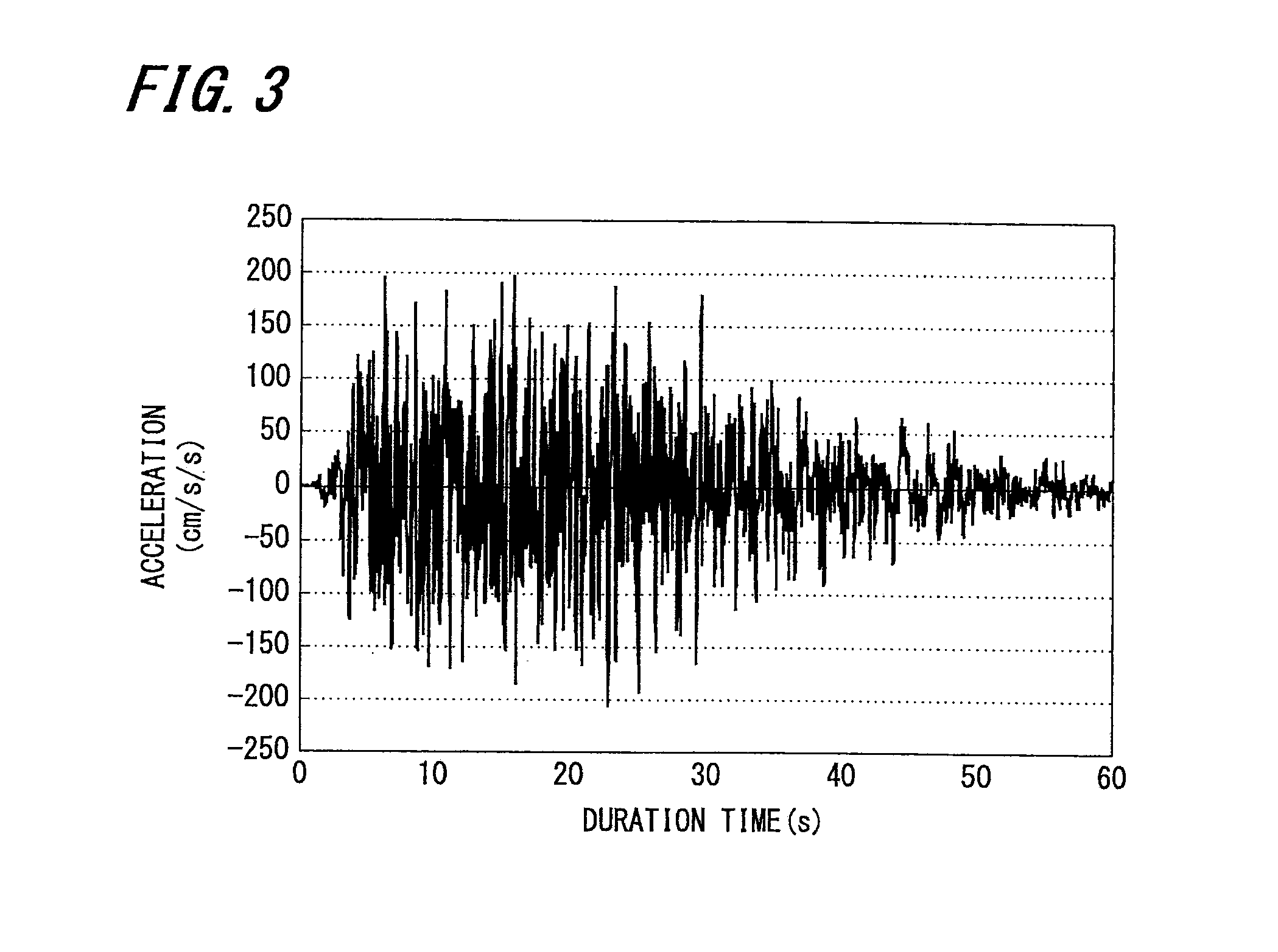
[0024]An embodiment of the present invention will be described below with reference to the attached drawings. In the present embodiment, description will be made using an example (referred to as “the present example” hereinafter) applied to a relocation detection unit 1 attached to an apparatus to detect the relocation of the apparatus by detecting the acceleration generated in the apparatus.

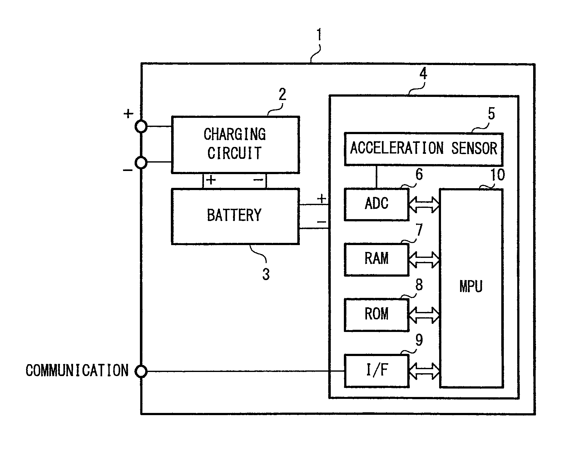
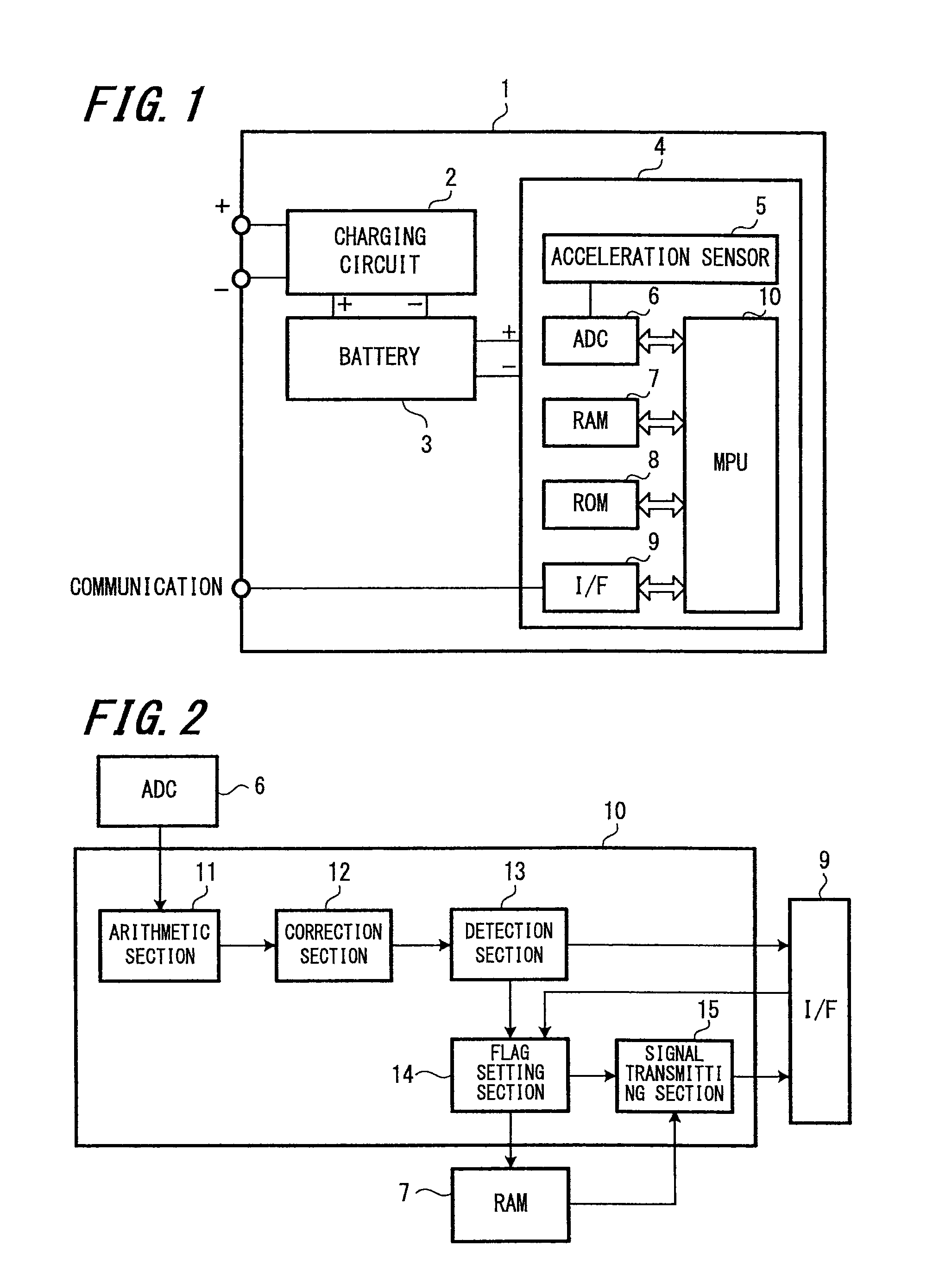
[0025]FIG. 1 is a block diagram showing an example of the internal configuration of the relocation detection unit 1.

[0026]The relocation detection unit 1 having an acceleration sensor 5 with one or more axes is attached to the apparatus (not shown in the drawings). A three-axis acceleration sensor for detecting acceleration in three axes is typically used as the acceleration sensor 5.

[0027]The relocation detection unit 1 includes a battery (a secondary battery) 3 and a charging circuit 2 for charging the battery 3, so that the relocation detection unit 1 keeps functioning even when the power sou...


PUM


Abstract

A relocation detection unit includes: an acceleration sensor adapted to detect acceleration generated in the apparatus, an arithmetic section adapted to obtain a first calculation value by performing Nth-order integration on detected value of the acceleration sensor at a predetermined timing, wherein N is a predetermined positive integer, a correction section adapted to obtain a second calculated value by adding / subtracting a specific value to / from the first calculation value at the predetermined timing, and a detection section adapted to detect that the apparatus has been relocated if the second calculated value exceeds a preset reference value.

Description

CROSS REFERENCES TO RELATED APPLICATIONS[0001]The present invention contains subject matter related to Japanese Patent Application JP 2010-172730 filed in the Japanese Patent Office on Jul. 30, 2010, the entire contents of which being incorporated herein by reference.BACKGROUND OF THE INVENTION[0002]1. Field of the Invention[0003]The present invention relates to a relocation detection method preferably used to detect relocation of an apparatus such as a machine tool or the like (referred to as an “apparatus” hereinafter), and a relocation detection unit.[0004]2. Description of the Related Art[0005]As cargoes possible to be used to develop weapons of mass destruction and the like, apparatuses with high accuracy and / or high function are strictly controlled so as not to be illegally exported. However, once an apparatus has been exported abroad, it is difficult to prevent the apparatus from being relocated to a country, to which the apparatus is not permitted to be exported, by a third ...

Claims


Application Information

Patent Timeline
Patent Type & Authority Patents(United States)
IPC IPC(8): G01P15/00
CPCG01P13/00G01P1/127G01P7/00
Inventor ONO, KATSUHIKO
Owner DMG MORI CO LTD
Why Eureka
Try Eureka