Motor vehicle steering system

a steering system and motor vehicle technology, applied in the direction of electric steering, power driven steering, vehicle components, etc., can solve the problem that the steering shaft can be reliably restricted from rotating inexpensively, and achieve the effect of reliably restricting the steering shaft from rotating inexpensively

Inactive Publication Date: 2014-09-09
JTEKT CORP
View PDF20 Cites 4 Cited by
  • Summary
  • Abstract
  • Description
  • Claims
  • Application Information

AI Technical Summary

Benefits of technology

[0026]According to the aspect of the present invention, the central axes of the end portions of the steered shaft supported by the bushings are offset from the central axis of the intermediate portion. Therefore, even without forming the end portions of the steered shaft and the bushings to have odd-shaped sections, for example, D-shaped sections, etc., the steered shaft can be restricted from rotating by bushings having simple shapes, for example, circular bushings. Therefore, the steered shaft can be reliably restricted from rotating inexpensively. The present invention that restricts the steered shaft from rotating is also applicable to a rack-pinion motor vehicle steering system and a steer-by-wire motor vehicle steering system.

Problems solved by technology

Therefore, the steered shaft can be reliably restricted from rotating inexpensively.

Method used


Image

  • Motor vehicle steering system
  • Motor vehicle steering system
  • Motor vehicle steering system

Examples


Embodiment Construction

[0037]Preferred embodiments of the present invention will be described with reference to the accompanying drawings.

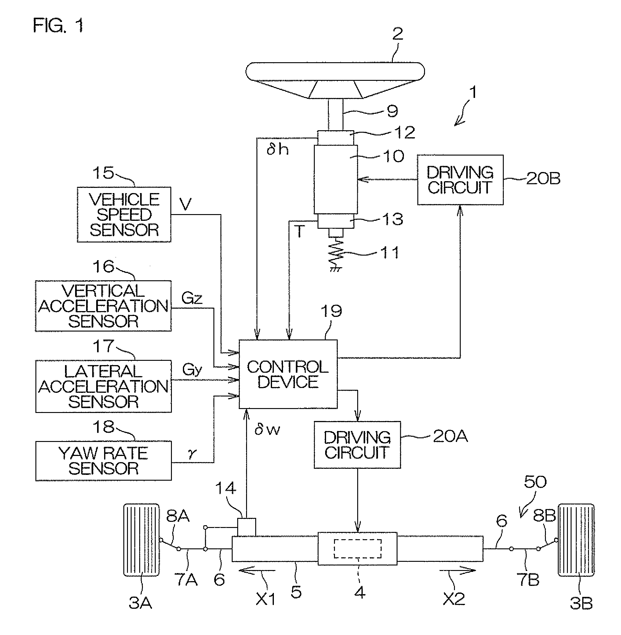
[0038]FIG. 1 is a schematic view showing a general configuration of a motor vehicle steering system according to a preferred embodiment of the present invention. Referring to FIG. 1, this motor vehicle steering system 1 composes a so-called steer-by-wire system in which the mechanical coupling between the steering member 2 such as a steering wheel and the steered wheels 3 is cut off.

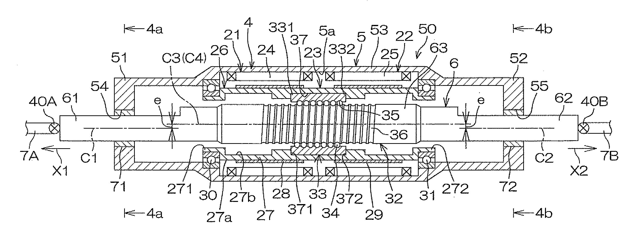
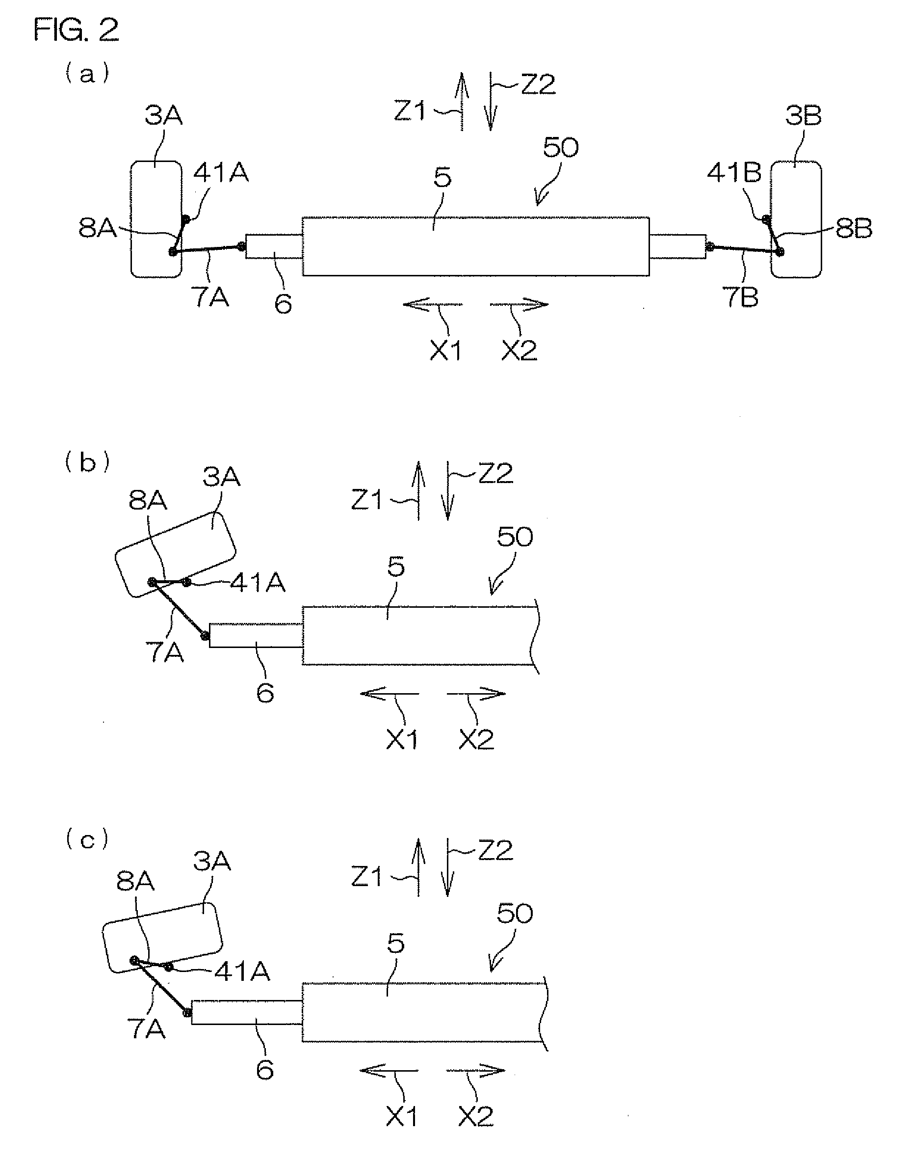
[0039]An operation of a turning actuator 4 that is driven according to a rotating operation of the steering member 2 and includes, for example, a brushless electric motor converted into linear motion in the vehicle width direction of the steered shaft 6 supported by the housing 5, and this linear motion of the steered shaft 6 is converted into a turning motion of the left and right steered wheels 3 for steering, and accordingly, turning is achieved.

[0040]A driving force (a rotating force of ...


PUM


Abstract

A motor vehicle steering system includes a steered shaft inserted through a tubular housing and a screw shaft provided on the intermediate portion of the steered shaft. A ball nut threadably engaged on the screw shaft via balls is driven to rotate by electric motors. A first bushing and a second bushing held by the housing support the first end portion and the second end portion of the steered shaft slidably in the axial direction, respectively. The central axis of the intermediate portion of the steered shaft is offset from the central axis of the first end portion and the central axis of the second end portion of the steered shaft. The central axis of the ball nut and the central axis of the intermediate portion of the steered shaft match each other.

Description

BACKGROUND OF THE INVENTION[0001]1. Field of the Invention[0002]The present invention relates to a motor vehicle steering system.[0003]2. Description of Related Arts[0004]In the rack-and-pinion electric power steering system disclosed in Patent Document 1 listed below, a bushing that supports an end portion of a rack shaft movably has an odd sectional shape at the inner periphery so as not to constrain the rack shaft in a direction perpendicular to the axis of the rack shaft and perpendicular to the rack pitch surface of the rack teeth. In detail, the bushing is formed into a slot whose diameter in the direction perpendicular to the rack pitch surface is larger than the diameter in the direction parallel to the rack pitch surface.[0005]In Patent Document 1, under low load, the bushing does not constrain the rack shaft in the direction perpendicular to the rack pitch surface, and therefore, the rack shaft is supported at two points of the portion meshing with the pinion and the porti...

Claims


Application Information

Patent Timeline
Patent Type & Authority Patents(United States)
IPC IPC(8): B62D5/04
CPCB62D5/0448B62D5/0427
Inventor TASHIRO, TAKASHI
Owner JTEKT CORP
Why Eureka
Try Eureka