Coated keybar to protect electric machines

a keybar and key technology, applied in the direction of screws, threaded fasteners, magnetic circuit shapes/forms/constructions, etc., to achieve the effect of preventing derating of the machine, preventing the core from failing, and preventing the hot spot in the cor

Inactive Publication Date: 2014-09-09
RAO DANTAM K
View PDF29 Cites 6 Cited by
  • Summary
  • Abstract
  • Description
  • Claims
  • Application Information

AI Technical Summary

Benefits of technology

[0013]A major object of the present invention is to protect the machine against damage caused by fault currents, keybar currents and throughbolt currents. Another object is to prevent hot spots in the core. Another object is to prevent core failure. Another object is to prevent derating of the machine caused by harmful eddy currents circulating within the core. Another object is to eliminate the need for core-fault detection equipment. Another object is to eliminate the need for recoating the laminations. Another object is to prevent core-end overheating during over-fluxing. Another object to protect the machine at higher leading power factor operating condition. Another object is to protect the machine under severe open circuit conditions. Another object is to protect the machine under severe short-circuit conditions. Another object is to reduce eddy currents from flowing through keybars. Another object is to eliminate devices to limit the Keybar Current. Another object is to prevent core decompression. Another object is to prevent loose laminations. Another object is to increase the efficiency. Another object is to reduce core losses. These objects and other benefits will be apparent to a person skilled in the art on perusal of the disclosed invention.
[0015]One embodiment of the invention is a high-resistivity coating over the surface of an uncoated keybar. The dovetail portion of the coated keybar fits snugly inside a matching dovetail slot of laminations over the plated surface. The bolt portion of the coated keybar is welded to frame rings over the coated surface. The coating forces the fault current or keybar current to pass through the high resistivity coating layer. The high resistance of the coating inserted into the electrical circuits substantially weakens them, thereby suppressing the core failure or core end heating. Optionally the coating can be applied with gaps matching the ventilation gaps in the core. This prevents potential delamination of the coating. In a similar fashion one can apply a high-resistivity coating over a prior-art uncoated throughbolt. This forces the eddy currents induced in the though-bolt to pass through the coating, whose high resistivity suppresses the eddy currents.

Problems solved by technology

The high resistance of the coating inserted into the electrical circuits substantially weakens them, thereby suppressing the core failure or core end heating.

Method used


Image

  • Coated keybar to protect electric machines
  • Coated keybar to protect electric machines
  • Coated keybar to protect electric machines

Examples


embodiment 100

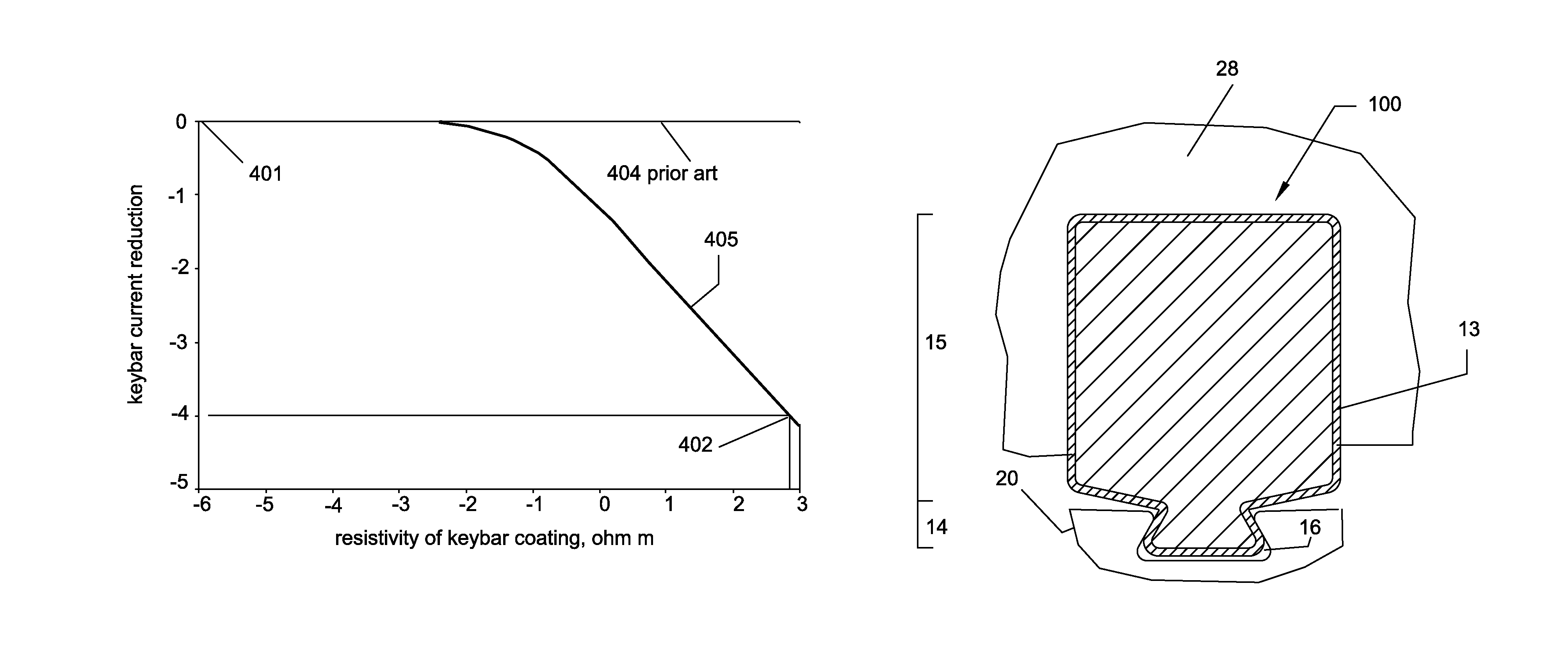
[0034]FIG. 4A shows the cross-section of a coated keybar embodiment 100. This coated keybar 100 is built by applying a high-resistivity coating 13 over the surface of a conventional keybar 10. The coating's surface resistance ranges 25 to 250 Ωcm2. Its thickness ranges 0.001″ to 0.030″. Its resistivity ranges 1 to 1000 Ωm. A thinner coating will have higher resistivity and thicker coating will have lower resistivity. The exposed surface of the keybar 100 has substantially higher resistance than the underlying keybar 10. The coated keybar 100 is subdivided into a coated dovetail 14 and a coated bolt 15 as shown.

[0035]FIG. 4B shows how the coated keybar 100 attaches to the laminations and the frame ring or flange. The coated dovetail 14 attaches to the laminations 20 while the coated bolt 15 attaches to other components such as flange or frame rings. The coated dovetail 14 fits snugly inside a matching dovetail slot 16 in the lamination 20. The high-resistivity slanted faces of the co...

embodiment 200

[0039]FIG. 5 shows a coated throughbolt embodiment 200 in accordance with the present invention. This coated throughbolt 200 comprises a conventional throughbolt with a high-resistivity coating 220. The exposed surface of the coated throughbolt 200 has substantially higher resistivity than the underlying throughbolt 210. The coated throughbolt 200 is inserted through an identical hole in the laminations and flanges 240 as shown. The surface of the high-resistivity coating 220 is in electrical contact with the flanges and laminations. The eddy currents generated in the throughbolt must pass through this high-resistivity coating 220 which weakens them. The weakened throughbolt currents reduce their operating temperature, hence prevent core-decompression and subsequent loosening of laminations.

[0040]The high resistivity coating can be applied over a conventional uncoated keybar 10 by electro-deposition technique. Such plating can employ a standalone high resistivity material or combine...

embodiment 500

[0043]FIG. 6 shows an alternative embodiment 500 of the keybar in accordance with the present invention. This employs high-resistivity strips 18 wedged in a gap between the faces of the keybar dovetail and the dovetail slot 16 of laminations 20. Individual strips 19 are also wedged between the bolt portion of the keybar and the frame ring 28. These strips are made of a high resistivity material such as silicon carbide with surface resistance in the range discussed above. The strip need not be bonded to the faces of the dovetail, but can be wedged in the gap. Such high resistivity strip operates exactly like a coating to weaken the hazard currents. However, because since it is not attached to the keybar, a strip can avoid thermal expansion related issues.


PUM


Abstract

A keybar or clamping bolt with a high-resistivity coating to protect an electric machine. The coating engages the laminations, flanges and frame rings and forms a part of electrical circuits through which harmful eddy currents circulate. One class of eddy currents, viz., core-fault currents, due to edge burrs or insulation defects, are forced to flow through this coating. The high resistance of the coating weakens the fault currents, preventing creation of hotspots that can cause core failure. Such coated keybar is in inexpensive alternative to traditional recoating and / or core-fault detection. Another class of eddy currents, viz., keybar currents, caused by over-fluxing, are also forced to flow through this coating. The high resistance of the coating weakens the keybar currents, so prevents core-end overheating. A coated keybar also allows the machine to operate at higher leading power factor. It also prevents core-decompression hence protects the machine against loose laminations.

Description

FIELD OF THE INVENTION[0001]The present disclosure relates to protecting electric machines against destructive eddy currents caused by core-faults or overfluxing that can result in hotspots, core failure, core-end heating, core decompression or derating of the machine.BACKGROUND[0002]All motors, generators and transformers employ a stator core comprising a stack of compressed laminations. Means used to compress the laminations include clamping bolts or keybars as in U.S. Pat. Nos. 3,652,889; 4,564,779, throughbolts as in U.S. Pat. No. 7,223,920; 2010024461, welding as in U.S. Pat. No. 4,485,320, bonding as in U.S. Pat. Nos. 4,085,347, 4,123,678, cleating or interlocks as in U.S. Pat. No. 5,918,359.[0003]Small and medium sized electric machines often employ simple round-sectioned steel bolts to compress the laminations. Large dynamoelectric machines on the other hand employ custom bolts with a dovetail, termed keybars, to compress the laminations and attach them to the frame rings. T...

Claims


Application Information

Patent Timeline
Patent Type & Authority Patents(United States)
IPC IPC(8): H02K1/18F16B19/02F16B35/00
CPCF16B35/00F16B19/02H02K1/185H02K1/04H02K1/16H02K11/0089H02K11/40
Inventor RAO, DANTAM, K.
Owner RAO DANTAM K
Why Eureka
Try Eureka