Package bag with externally attached communication device

a communication device and packaging bag technology, applied in the field of packaging bags, can solve problems such as image pulse problems, complete destructive interference, and destructive interference, and achieve the effect of reducing the size and smallest siz

Inactive Publication Date: 2014-09-09
TAIWAN LAMINATION INDS
View PDF7 Cites 3 Cited by
  • Summary
  • Abstract
  • Description
  • Claims
  • Application Information

AI Technical Summary

Benefits of technology

[0008]It is an object of the present invention to provide a package bag having an externally attached communication device, wherein the package bag includes a surface material, a metal layer, and a bottom material, in addition to the communication device. The surface material is a film made of plastic and is provided with an outer groove. The metal layer has one surface coated on one surface of the surface material. The metal layer is formed with a first groove and a second groove, both corresponding in position to the outer groove. The first groove is adjacent to one edge of the metal layer. The second groove has a first side which extends to the aforesaid edge of the metal layer and a second side which is away from the aforesaid edge of the metal layer and communicates vertically with a central section of a first side of the first groove. The second side of the second groove is shorter than the first side of the first groove, such that the portions of the metal layer that are adjacent to the first side of the first groove form two first impedance-matching portions respectively. In addition, the two corresponding portions of the metal layer that are adjacent to the first groove form two second impedance-matching portions respectively. Thus, the first groove and the second groove of the metal layer form a slot antenna. The bottom material is a film made of plastic and has one surface coated on the other surface of the metal layer. The bottom material is provided with an inner groove corresponding in position to the slot antenna. The surface material, the metal layer, and the bottom material are connected to form a packaging material for making the package bag. The communication device is attached to the packaging material at a position corresponding to the slot antenna and can couple with the slot antenna, thereby forming an RFID tag on the packaging material. The fact that the slot antenna of the RFID tag is formed by the grooves of the metal layer effectively solves the problem of image pulses, which, as stated previously, are generated by a metal article and can render a conventional RFID tag incapable of RF signal transmission to and from a reader.
[0009]Another object of the present invention is to provide the foregoing package bag, wherein the communication device includes an attachment material, a conductive loop, and a communication chip. The attachment material has a larger configuration than the conductive loop, so as for the attachment material to attach the conductive loop to the package bag at a position corresponding to the first groove. The conductive loop is of a hollow and symmetric shape and includes two first conducting portions, two second conducting portions, two first connecting portions, and a second connecting portion. The first conducting portions correspond in position to the first impedance-matching portions respectively. Each first conducting portion has a first end connected to a first end of the corresponding second conducting portion. Each first conducting portion further has a second end connected to a first end of the corresponding first connecting portion. The second ends of the first connecting portions are spaced apart by a first distance, and the communication chip is provided at the second ends of the first connecting portions. The second conducting portions correspond in position to the second impedance-matching portions respectively. The second ends of the second conducting portions are in conduction with each other via the second connecting portion. Once the conductive loop is attached to the package bag, the first conducting portions do not overlap with the first impedance-matching portions, whereas the second conducting portions overlap with the second impedance-matching portions and can couple therewith respectively, thus forming the RFID tag. When the RFID tag receives an RF signal transmitted from a reader, the second conducting portions respectively and electromagnetically couple with the second impedance-matching portions such that two capacitive impedances are respectively generated therebetween. The second conducting portions are thus enabled to deliver the energy generated by electromagnetic induction of the slot antenna, so as for the data in the communication chip to be transmitted to the reader. As the RFID tag features optimization of coupling impedance-matching, the slot antenna can be effectively downsized. This allows the slot antenna to have the smallest size possible for achieving the desired transmission distance.

Problems solved by technology

When the RFID tag 1 is attached to the surface of a metal article, however, the metal article will, according to the image theory, generate image pulses which are in antiphase, and hence destructively interfere, with the RF signals transmitted by the transceiver antenna 12.
If the amplitude of a wave completely cancels the amplitude of a destructively interfering wave, complete destructive interference takes place.
However, as stated above, the image pulse problem arises when the RFID tag 1 is provided on a packaging material with a metal lining.
More particularly, attaching the RFID tag 1 to an electroplated aluminum foil bag will seriously compromise the readability of the RFID tag 1 or even reduce the read distance of the tag to approximately 0 meter, in which case the RFID tag 1 is practically unreadable.
Furthermore, electroplated aluminum foil bags are typically used to package articles of relatively small sizes and relatively short shelf lives, but it is difficult to design inexpensive and compact RFID tags for use on electroplated aluminum foil bags without impairing the low-cost and small-size features of the bags.
The lack of RFID tags suitable for use with electroplated aluminum foil bags adds to the inconvenience of logistics management.

Method used


Image

  • Package bag with externally attached communication device
  • Package bag with externally attached communication device
  • Package bag with externally attached communication device

Examples


Embodiment Construction

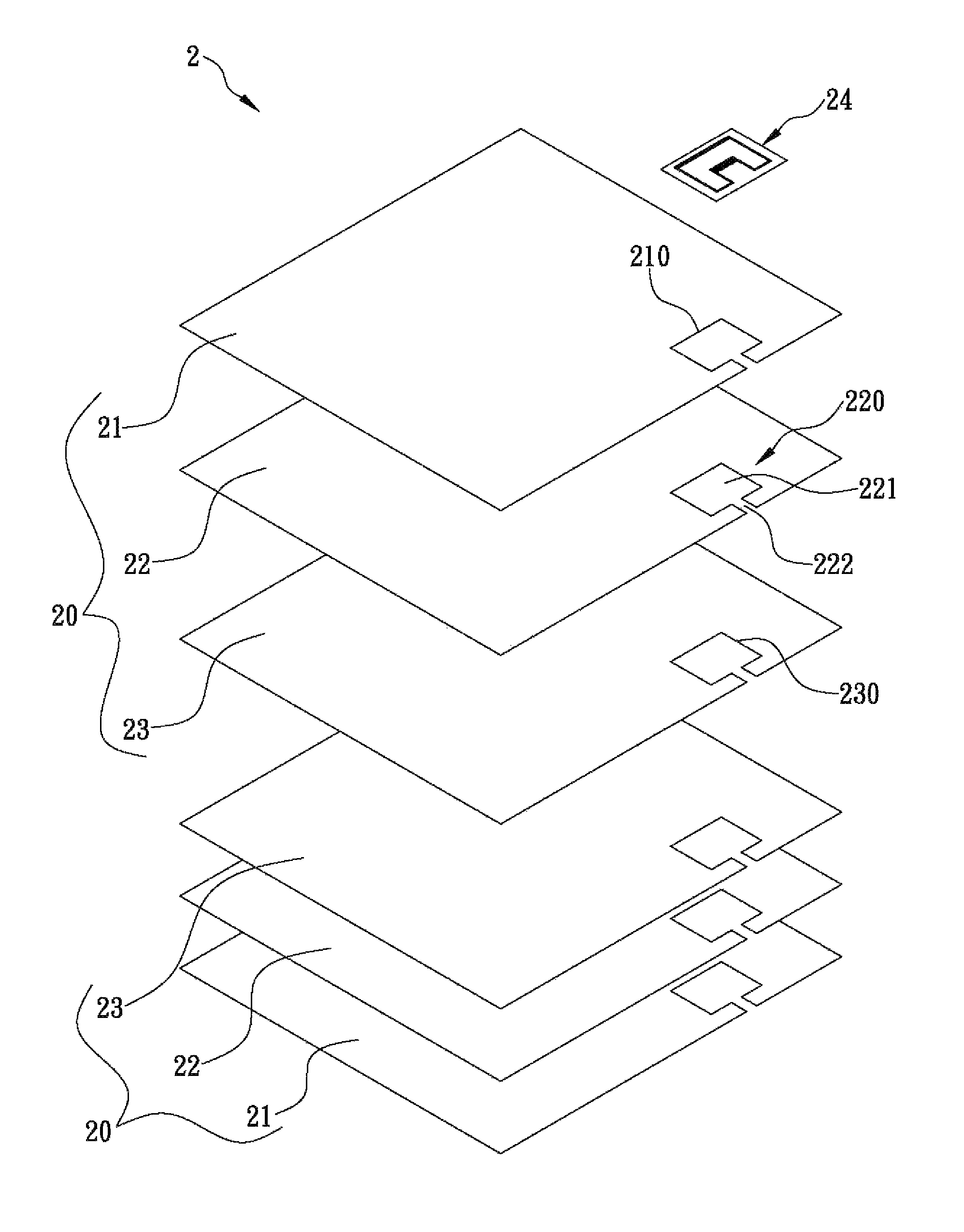
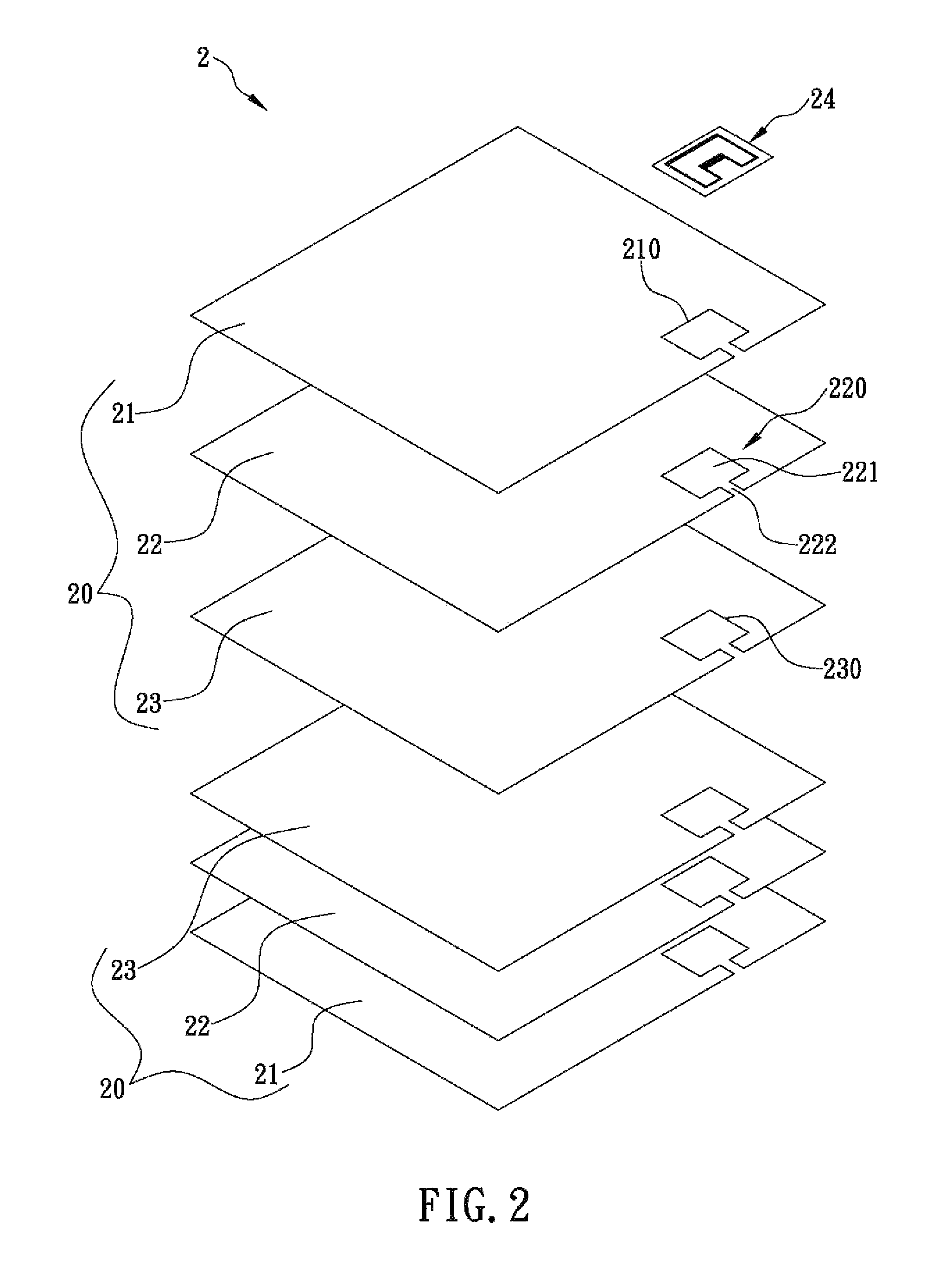
[0020]The present invention discloses a package bag with an externally attached communication device. Referring to FIG. 2 for the first preferred embodiment of the present invention, the package bag 2 includes a surface material 21, a metal layer 22, a bottom material 23, and a communication device 24. The surface material 21 is a film made of plastic. The metal layer 22 has one surface coated on one surface of the surface material 21. The bottom material 23 is also a film made of plastic (e.g., linear low-density polyethylene) and is coated on the opposite surface of the metal layer 22 such that the surface material 21, the metal layer 22, and the bottom material 23 are connected to form a packaging material 20 for making the package bag 2. It should be pointed out that the metal layer 22 is depicted in FIG. 2 as a film only to facilitate disclosure of the components of the package bag 2. In practice, the metal layer 22 may be attached to the surface material 21 by evaporation, spu...


PUM


Abstract

The present invention is to provide a package bag having a metal layer, wherein the metal layer is formed with a first groove and a second groove, and the second groove has a first side extending to one edge of the metal layer and a second side away from said edge and communicating vertically with a central section of a first side of the first groove. The second side of the second groove is shorter than the first side of the first groove, such that the portions of the metal layer adjacent to the first side of the first groove form two first impedance-matching portions respectively, and the two corresponding portions of the metal layer adjacent to the first groove form two second impedance-matching portions respectively. Thus, due to the impedance-matching portions, a slot antenna can be formed on the metal layer for coupling with a communication device attached thereto.

Description

FIELD OF THE INVENTION[0001]The present invention relates to a package bag, more particularly to a package bag having a communication device externally attached to a slot antenna formed thereon, wherein, since there are impedance-matching portions formed between the slot antenna and the communication device, the slot antenna can be made in a smallest size for achieving a desired transmission distance.BACKGROUND OF THE INVENTION[0002]Radio frequency identification (RFID) is a technology whereby specific targets can be identified, and related data can be read and written, via radio frequency (RF) signals. Thanks to the RFID technology, an RFID tag can be provided on the package bag of an article, so as for a reader within a predetermined distance from the article to obtain the data (e.g., the year of manufacture, the expiration date, etc.) stored in the RFID tag. Compared with barcode technology, RFID not only features a larger storage capacity, but also is more convenient to use, for...

Claims


Application Information

Patent Timeline
Patent Type & Authority Patents(United States)
IPC IPC(8): G08B13/14A24F27/00G06K9/00H01Q13/10G06K19/077H01Q1/22
CPCG06K19/07745H01Q13/10H01Q1/2225G06K19/07773G06K19/07771G06K19/07794H01L2924/0002H01L2924/00
Inventor CHEN, YUNG-SHUN
Owner TAIWAN LAMINATION INDS
Why Eureka
Try Eureka