
Stack-type vertical heat dissipation device

a vertical heat dissipation and stacking technology, applied in the field of stacking vertical heat dissipation devices, can solve the problems of failure of devices or power, rapid device temperature increase, and electronic devices involved are subject to not only requirements in heat dissipation efficiency, but also requirements in volume, size, and dimensions

Active Publication Date: 2022-03-10
MAN ZAI IND
View PDF4 Cites 0 Cited by
  • Summary
  • Abstract
  • Description
  • Claims
  • Application Information

AI Technical Summary

Benefits of technology

The present invention has the advantage of higher heat dissipation efficiency, allowing for smaller end products and increased practicality. Additionally, the structure of the invention can withstand higher pressure from being overfilled with a heat conduction medium, increasing safety and service life. Finally, vertical stacking improves the circulation efficiency of the heat conduction medium, reducing clogging when the medium cools down.

Problems solved by technology

Otherwise, the temperature of the devices will increase rapidly when the heat accumulation rate is higher than the heat dissipation efficiency, which results in failure of device or power.
When it comes to the servers in a data center, however, the electronic devices involved are subject to not only requirements in heat dissipation efficiency, but also requirements in volume, size, and dimensions due to the limitations on space allocation.
It is therefore important to find ways to achieve optimal heat dissipation efficiency in a limited space and meet manufacturers' requirements as well, and this is obviously an issue in the related industries that needs to be addressed persistently.

Method used


Image

  • Stack-type vertical heat dissipation device
  • Stack-type vertical heat dissipation device
  • Stack-type vertical heat dissipation device

Examples


first embodiment

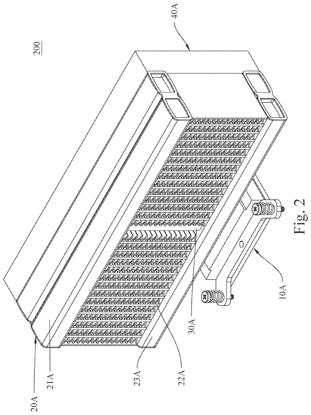
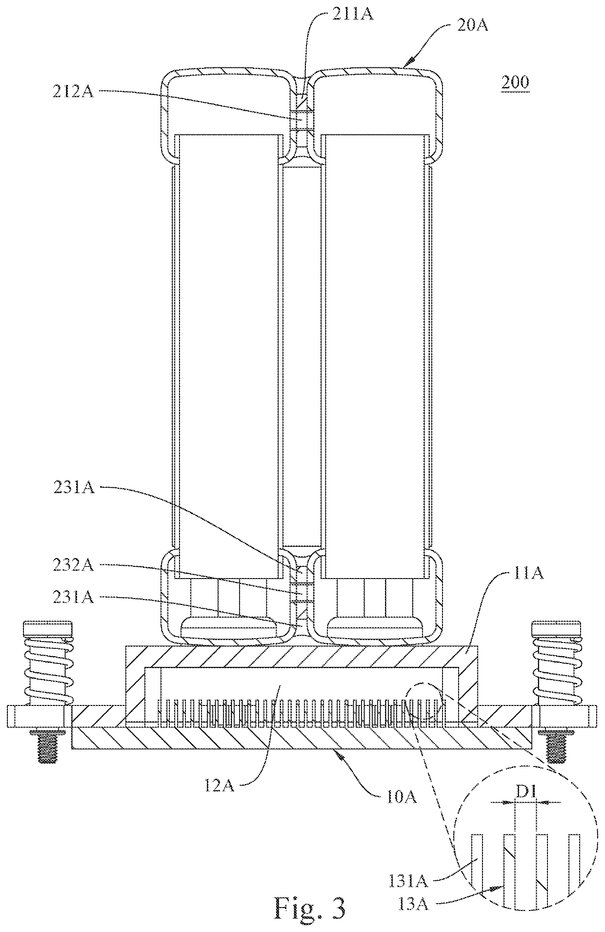
[0059]The following paragraphs describe an embodiment of the present invention with reference to FIG. 2, FIG. 3, and FIG. 4, which show a perspective view, a sectional view, a partial enlarged view, and another sectional view of the invention.

[0060]The stack-type vertical heat dissipation device 200 according to the first embodiment essentially includes an evaporator unit 10A, a condenser unit 20A coupled to the top side of the evaporator unit 10A, and a fan unit 40A provided on one side of the condenser unit 20A.

[0061]The evaporator unit 10A essentially includes a housing 11A, an evaporation chamber 12A provided inside the housing 11A, and a skived structure 13A provided in the evaporation chamber 12A. In one preferred embodiment, the housing 11A may be made of aluminum, an aluminum alloy, or other similar materials; the present invention has no limitation in this regard.

[0062]The skived structure 13A includes a plurality of skived plates 131A that are formed on the inner bottom si...

second embodiment

[0071]Another embodiment of the present invention is described below with reference to FIG. 7, FIG. 8, and FIG. 9, which show a perspective view, a partial sectional view, a sectional view, and a partial enlarged view of the invention.

[0072]The stack-type vertical heat dissipation device 300 according to the second embodiment essentially includes an evaporator unit 10B, a condenser unit 20B coupled to the top side of the evaporator unit 10B, and a fan unit 30B provided on one side of the condenser unit 20B.

[0073]The evaporator unit 10B essentially includes a first housing 11B, an evaporation chamber 12B provided inside the first housing 11B, and a skived structure 13B provided in the evaporation chamber 12B. In one feasible embodiment, the first housing 11B may be made of aluminum, an aluminum alloy, or other similar materials; the present invention has no limitation in this regard. In one feasible embodiment, the first housing 11B of the evaporator unit 10B is provided with a plura...

third embodiment

[0084]Yet another embodiment of the present invention is described below with reference to FIG. 13, FIG. 14, and FIG. 15, which show a perspective view, a partial sectional view, a sectional view, and some partial enlarged views of the invention.

[0085]The stack-type vertical heat dissipation device 400 according to the third embodiment essentially includes an evaporator unit 10C, a condenser unit 20C coupled to the top side of the evaporator unit 10C, and a fan unit 30C provided on one side of the condenser unit 20C.

[0086]The evaporator unit 10C essentially includes a housing 11C, an evaporation chamber 12C provided inside the housing 11C, and a skived structure 13C provided in the evaporation chamber 12C. In one preferred embodiment, the housing 11C may be made of aluminum, an aluminum alloy, or other similar materials; the present invention has no limitation in this regard.

[0087]The skived structure 13C includes a plurality of skived plates 131C that are formed on the inner bottom...


PUM


Abstract

The present invention provides a stack-type vertical heat dissipation device comprising an evaporator unit and a condenser unit. The evaporator unit has a side configured for direct or indirect contact with, and thereby receiving heat from, a high-temperature device in order for the heat to convert a heat conduction medium inside the evaporator unit into a gaseous state. The condenser unit is stacked on a top side of a housing of the evaporator unit, and is provided therein with a flow channel that is in communication with the evaporator unit and allows passage of the heat conduction medium so that the heat conduction medium is able to return to the evaporator unit under a force of gravity after condensing from the gaseous state into a liquid state and thereby complete a thermal cycle.

Description

BACKGROUND OF THE INVENTION1. Technical Field[0001]The present invention provides a heat dissipation device, in particular a stack-type vertical heat dissipation device.2. Description of Related Art[0002]Under normal circumstances, there is a high correlation between the performance of electronic products and temperature. The performance of electronic products decreases while the temperature increases. In practice, most of the electronic products components that tend to generate high heat are processors and chips. Generally, the operation temperature of processors and chips in the manufacturing process is approximately between 110° C. and 200° C. The operation temperature must be even higher than 230° C. in order to melt the solder during the soldering process. Accordingly, the processor or the chip will not be damaged under a certain temperature in principal.[0003]However, many high-power devices, such as servers in data centers, must operate continuously at high power in order to ...

Claims


Application Information

Patent Timeline
Patent Type & Authority Applications(United States)
IPC IPC(8): H05K7/20
CPCH05K7/20309H05K7/20318H05K7/20409H05K7/20509H05K7/20145H01L23/427H01L23/4006H01L23/3672F28D15/025F28D15/0266F28D15/0275F28D2021/0029F28D2021/0031F28D1/05333F28D15/046
Inventor WAN, CHENG-CHIENWAN, CHENG-JUISU, CHUN-HSIENHUANG, HUI-FEN
Owner MAN ZAI IND
Learn More