Image capturing apparatus and control method thereof

a technology of image capturing and control methods, applied in the field of image capturing apparatuses and control methods thereof, can solve the problems of increasing the number of output channels, increasing the complexity of signal delay amount adjustment between channels, and increasing the burden on systems, so as to shorten the readout time of an image signal

Inactive Publication Date: 2014-09-09
CANON KK
View PDF7 Cites 6 Cited by
  • Summary
  • Abstract
  • Description
  • Claims
  • Application Information

AI Technical Summary

Benefits of technology

[0006]The present invention has been made in consideration of the above situation, and shortens the readout time of an image signal from an image sensor while making it possible to set a focus control area in a desired region within the image sensor.

Problems solved by technology

However, with an increase in the number of pixels in image sensors, it is necessary to read out a great number of pixel signals within a predetermined amount of time; on the other hand, systems are experiencing increasing burdens due to increases in the output rates of image sensors, increases in the number of output channels, and so on.
For example, there is a problem in that the complexity of signal delay amount adjustment between channels increases due to an increase in the number of output channels or an increase in the signal output rate.
Because such a configuration increases the number of signal readouts, the system will experience an increased burden particularly in the case of an image sensor in which single pixels are configured of multiple photoelectric converters and a pupil division readout function is provided.

Method used


Image

  • Image capturing apparatus and control method thereof
  • Image capturing apparatus and control method thereof
  • Image capturing apparatus and control method thereof

Examples


first embodiment

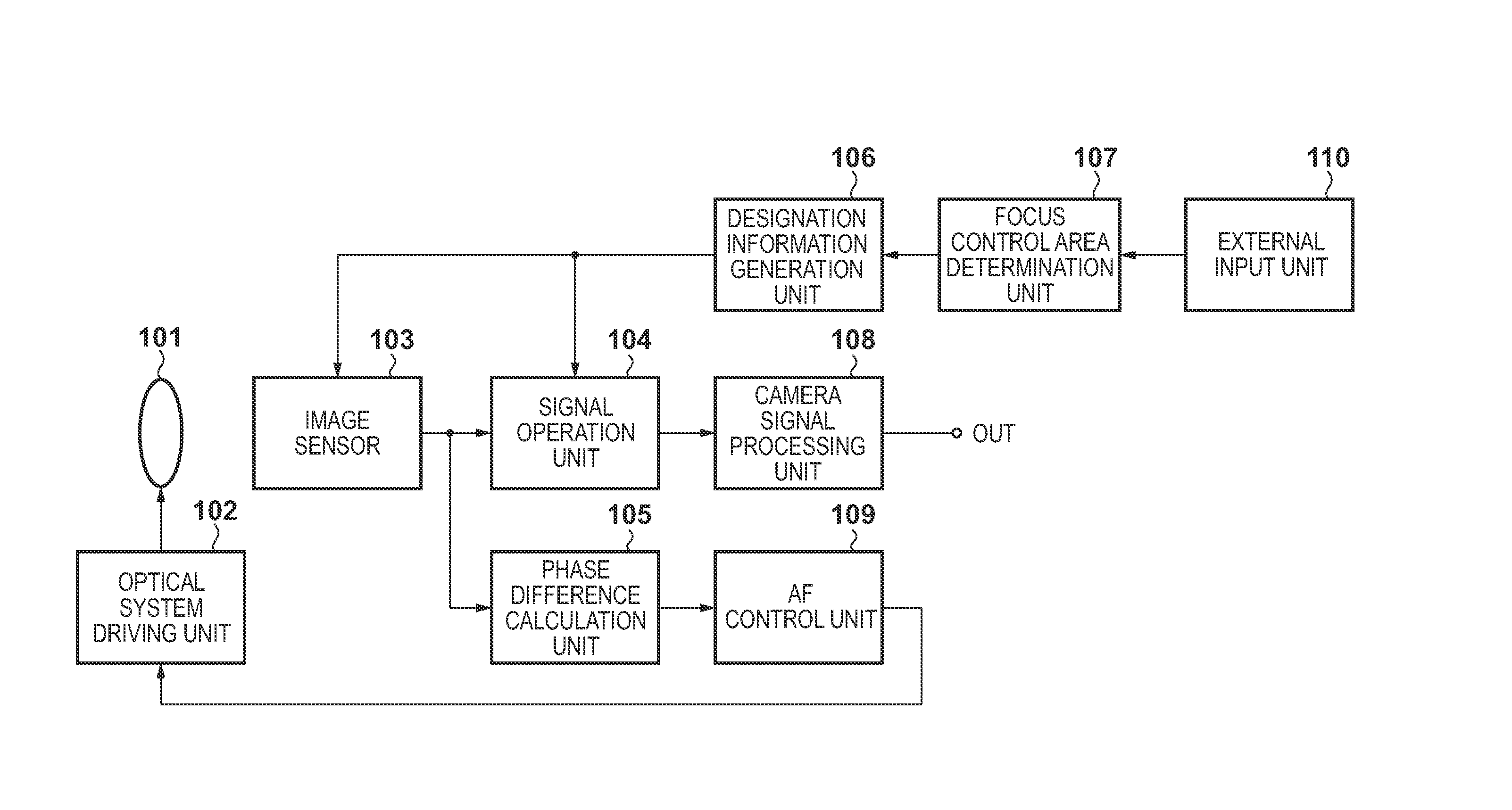
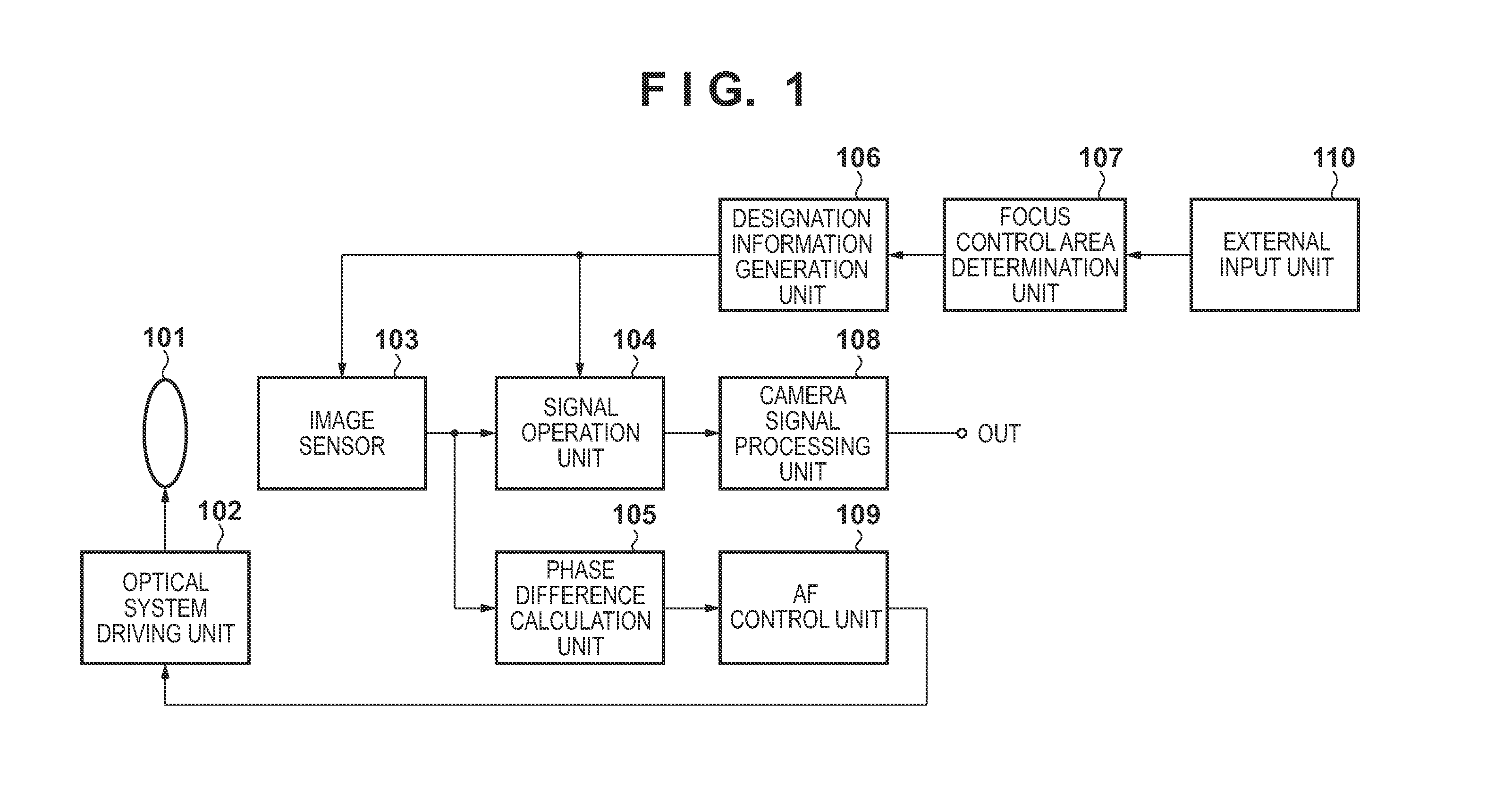
[0030]FIG. 1 is a block diagram illustrating a brief configuration of an image capturing apparatus according to a first embodiment of the present invention. In FIG. 1, an optical system 101 includes a focus lens and furthermore includes a zoom lens, an aperture, and so on, and an optical system driving unit 102 controls the optical system 101, using control signals, in accordance with optical system driving information output from an AF control unit109, which will be mentioned later.

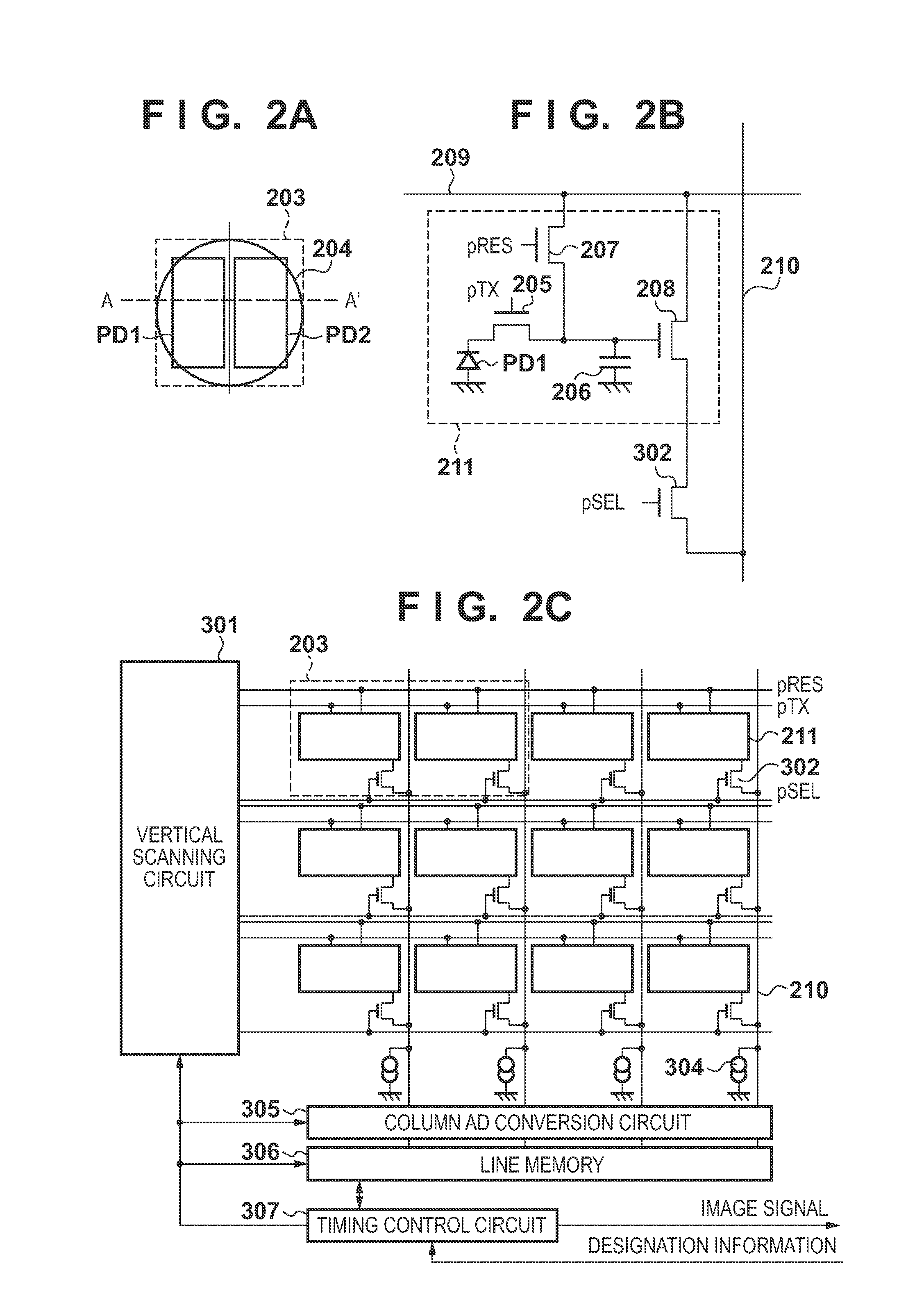
[0031]An image sensor 103 converts a subject image into an electrical signal through photoelectric conversion and outputs the resulting signal as an image signal, and the image signal is read out in accordance with designation information output from a designation information generation unit 106, which will be described later. In the present first embodiment, as will be described later, each pixel includes multiple photoelectric converters, each of which receives light beams that have passed through diff...

second embodiment

[0060]Next, a second embodiment of the present invention will be described. FIG. 8 is a block diagram illustrating a brief configuration of an image capturing apparatus according to the second embodiment. In the aforementioned first embodiment, the focus control area designated by the user is input through the external input unit 110; the second embodiment differs from the first embodiment in that the image capturing apparatus automatically determines the focus control area. Accordingly, the configuration differs in that instead of the external input unit 110 and the focus control area determination unit 107 illustrated in FIG. 1, an edge component detection unit 801 has been added, as shown in FIG. 8. Other constituent elements that are the same as those illustrated in FIG. 1 are given the same reference numerals, and descriptions thereof are omitted.

[0061]In the second embodiment, the edge component detection unit 801 detects edge components contained in the image signals based on...

third embodiment

[0067]Next, a third embodiment of the present invention will be described. FIG. 12 is a block diagram illustrating a brief configuration of an image capturing apparatus according to the third embodiment. In the aforementioned second embodiment, the focus control area is determined based on edge components detected from the display / recording image; the present third embodiment differs in that the face of a main subject contained in a display / recording image is detected, and the focus control area is determined based on the detected face. Accordingly, in FIG. 12, a subject face detection unit 1201 has been added in place of the edge component detection unit 801 indicated in FIG. 8. Other constituent elements that are the same as those illustrated in FIG. 8 are given the same reference numerals, and descriptions thereof are omitted.

[0068]In the third embodiment, the subject face detection unit 1201 detects the face of a subject from the display / recording image, determines an area that ...


PUM


Abstract

An image capturing apparatus comprises: an image sensor including multiple pixels, each having pupil-divided multiple photoelectric converters, a storage unit that stores the respective pupil-divided image signals, and a control unit, and an operation of adding the image signals on a pixel-by-pixel basis and outputting the resulting signal; a determination unit configured to determine a focus control area, using an image expressed by the image signal output from the image sensor; and a focus control unit configured to carry out focus control according to the phase difference detection method based on the pupil-divided image signals output from the pixels within the focus control area, wherein the control unit switches between an operation of individually outputting the pupil-divided image signals within the focus control area, and an operation of adding and outputting the pupil-divided image signals output from pixels outside of the focus control area on a pixel-by-pixel basis.

Description

BACKGROUND OF THE INVENTION[0001]1. Field of the Invention[0002]The present invention relates to image capturing apparatuses and control methods thereof, and particularly relates to image capturing apparatuses capable of reading out a pair of signals based on light beams from pixels that have passed through different pupil areas of an optical system, and to control methods thereof.[0003]2. Description of the Related Art[0004]Techniques for implementing both a focus detection function and image signal acquisition using a single image sensor have been known for some time, and a technique in which information acquisition pixels for focus detection can also be used as image acquisition pixels for acquiring an image signal has been proposed as an example of such (for example, see Japanese Patent Laid-Open No. 2007-325139). According to this technique, the information acquisition pixels are divided into four regions in the horizontal and vertical directions, and when an image is to be acq...

Claims


Application Information

Patent Timeline
Patent Type & Authority Patents(United States)
IPC IPC(8): H04N5/76G02B7/28G02B7/34G03B13/36H04N5/232
CPCG02B7/28G02B7/34H04N5/232G03B13/36H04N5/3696H04N5/772H04N23/672H04N23/673H04N23/675H04N25/702
Inventor NAKAOKA, HIROSHI
Owner CANON KK
Why Eureka
Try Eureka