Correlated imaging system

A technology for associating imaging and imaging objects, applied in optical components, optics, instruments, etc., can solve the problems of low camera exposure frame rate and large data volume, and achieve the effects of saving computing time, improving efficiency, and shortening imaging time

Active Publication Date: 2014-07-30
INST OF PHYSICS - CHINESE ACAD OF SCI
View PDF3 Cites 18 Cited by
  • Summary
  • Abstract
  • Description
  • Claims
  • Application Information

AI Technical Summary

Problems solved by technology

[0003] The disadvantage of correlative imaging technology is that the amount of data required to reconstruct the image is large, about 10 4 The magnitude of sampling, while the current camera exposure frame rate is low, generally 60 frames per second, the contradiction between the two has become a bottleneck for real-time correlated imaging

Method used


Image

  • Correlated imaging system
  • Correlated imaging system
  • Correlated imaging system

Examples


Embodiment Construction

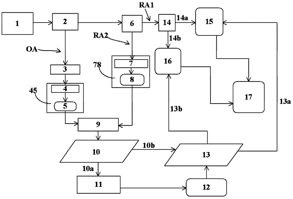
[0038] figure 1 is a schematic structural layout diagram of an associated imaging system according to an embodiment of the present invention. figure 1 The associated imaging system in may include an object arm optical path OA, a first reference arm optical path RA1 and a second reference arm optical path RA2. There may be a first barrel detector 45 and an object 3 to be imaged in the object arm optical path OA. The first barrel detector 45 is used to sample the total light field intensity signal S after passing through the object 3 to be imaged in the object arm optical path OA m . The first reference arm optical path RA1 has a reference detector device for sampling the optical field intensity distribution information of the first reference arm optical path RA1. The reference detector arrangement can have a plurality of reference detector units. exist figure 1 In the exemplary embodiment shown, the reference detector arrangement has a first reference detector unit 15 and ...


PUM


Abstract

The invention provides a correlated imaging system used for carrying out correlated imaging on an object to be imaged through a thermal light source. The correlated imaging system comprises an object arm light path and a first reference arm light path, wherein the object arm light path is internally provided with a first barrel detector and the object to be imaged; the first barrel detector samples a total light field intensity signal Sm, passing through the object to be imaged, in the object arm light path; the first reference arm light path is provided with a reference detector device for sampling the distribution information of the light field intensity of the first reference arm light path; the reference detector device comprises at least one reference detector unit; each reference detector unit comprises a timing sequence controller and a plurality of reference detectors with the spatial resolving power; the reference detectors are controlled by the timing sequence controller; the reference detectors are exposed in sequence for sampling under the control of the timing sequence controller. As the reference detectors are alternately exposed in time sequence, the exposure frame rates can be overlapped, limitation of existing reference detectors on the sampling speed is broken through, the sampling speed is greatly increased, and the imaging time is shortened.

Description

technical field [0001] The invention relates to light field imaging technology, in particular to an associated imaging system. Background technique [0002] Correlation imaging technology (also known as "ghost" imaging) is a technology based on the second-order correlation characteristics of thermal optical field or quantum optical field to reconstruct object information in a non-localized manner. According to the different statistical properties of the light field, correlation imaging can be divided into quantum imaging and thermo-optic correlation imaging, but the imaging results achieved by the two are consistent. Since thermal light sources (such as sunlight) are closely related to our daily life, the research direction tends to be associated imaging technology based on thermal light sources. In recent years, the correlative imaging technology based on thermal light source has been developed rapidly. Different from traditional lens imaging or camera technology, the corr...

Claims


Application Information

Patent Timeline
Patent Type & Authority Applications(China)
IPC IPC(8): G02B27/00
Inventor 李明飞吴令安
Owner INST OF PHYSICS - CHINESE ACAD OF SCI
Why Eureka
Try Eureka