Image processor and image processing method generating first and second multi-value density data or performing quantization based on an image characteristic

a multi-value density and image technology, applied in the direction of digitally marking record carriers, visual presentation using printers, instruments, etc., can solve the problems of density fluctuation and density unevenness, deviation of the dot printing position between, and defects in the image, so as to suppress both unevenness

Active Publication Date: 2014-09-09
CANON KK
View PDF15 Cites 20 Cited by
  • Summary
  • Abstract
  • Description
  • Claims
  • Application Information

AI Technical Summary

Benefits of technology

[0009]Taking into consideration the knowledge described above, the object of the present invention is to suppress both unevenness due to changes in density (unevenness due to density fluctuation) and graininess.

Problems solved by technology

However, recently, even by adopting the multipass printing method, deviation of the dot printing position may occur between that of a prior printing scan and that of a later printing scan due to fluctuation in the amount the printing medium is conveyed.
This kind of deviation causes fluctuation in the dot coverage rate, which causes defects in the image such as density fluctuation and density unevenness.
However, in the method disclosed in Japanese Patent Laid-Open No. 2000-103088, binary data are not correlated among a plurality of planes, so graininess may become worse.
However, in a configuration in which binary data are not correlated among a plurality of planes, the locations of overlapping dots (1603) and locations of dots printed adjacent to each other (1601, 1602) occur irregularly as illustrated in FIG. 10C, and an accumulation of these dots cause the graininess to become worse.
In other words, when the dispersion of the dots is increased in order to suppress graininess (keep the dot overlap rate low), unevenness occurs as the density changes, and when the dot overlap rate is increased in order to suppress the unevenness due to this density change, the graininess becomes worse.

Method used


Image

  • Image processor and image processing method generating first and second multi-value density data or performing quantization based on an image characteristic
  • Image processor and image processing method generating first and second multi-value density data or performing quantization based on an image characteristic
  • Image processor and image processing method generating first and second multi-value density data or performing quantization based on an image characteristic

Examples


embodiment 1

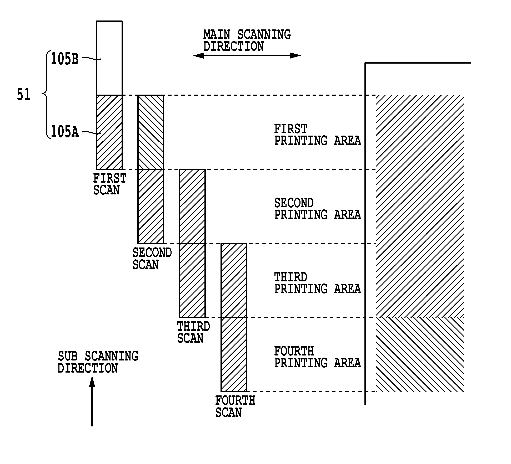
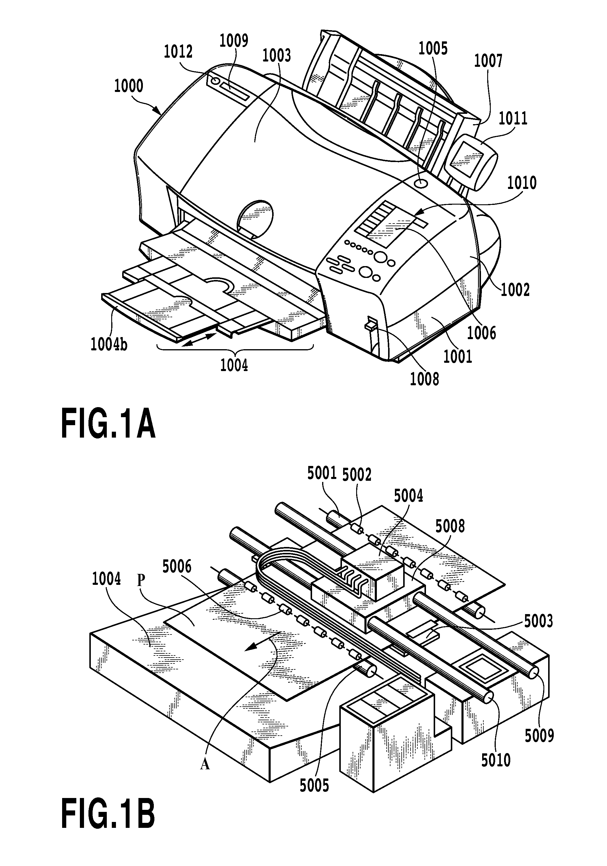
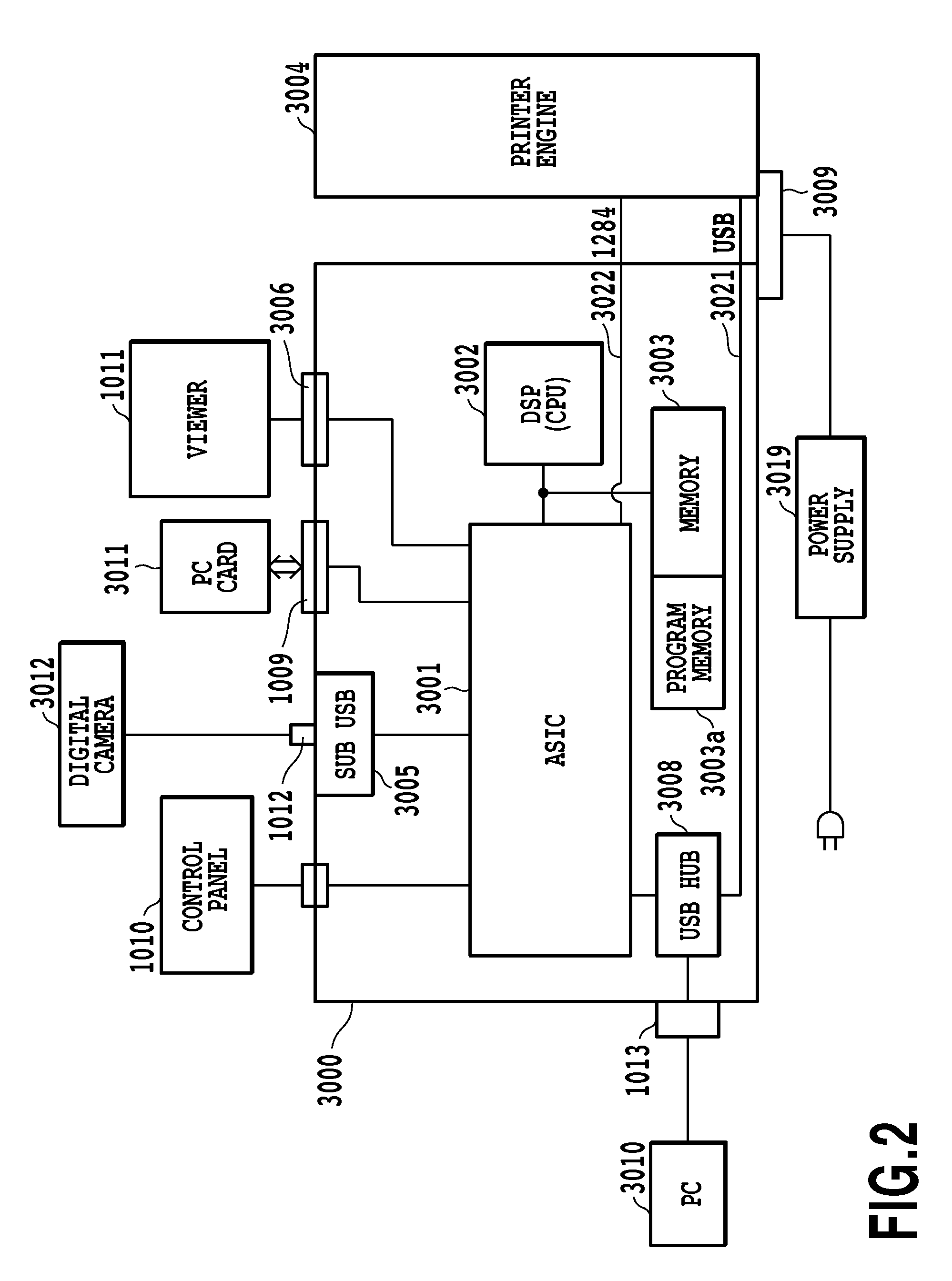
[0055]FIG. 3 is a block diagram for explaining image processing in the case of performing multipass printing to complete an image in the same area on a printing medium by two printing scans as illustrated in FIG. 7. A control unit 3000 comprises: a multi-value image data input unit (61), a color conversion / image data division unit (62), gradation correction processing units (63-1, 63-2) and quantization processing units (65-1, 65-2). On the other hand, a printer engine 3004 comprises binary data division processing units (67-1, 67-2).

[0056]When multi-value RGB image data (256 values) is inputted from an external device by way of the multi-value image data input unit 61, this inputted image data (original image) is sent to an image characteristic analysis / parameter setting unit 60. The image characteristic analysis / parameter setting unit 60 examines the entire original image and analyzes whether the original image is a portrait (first characteristic) or something else (characteristic...

embodiment 2

Variation of Embodiment 2

[0121]The quantization method for achieving the desired dot overlap rate is not limited to that described above. It is not absolutely necessary to set printing (1) and no printing (0) through comparison with threshold values. For example, in the case of two planes, a 2-dimensional table could also be prepared in which the values K1′ and K2′ are primarily set to printing (1) or no printing (0) by using both K1ttl and K2ttl as reference values. Moreover, in the case of three planes, a 3-dimensional table could also be prepared in which the values K1′, K2′ and K3′ are primarily set by using K1ttl, K2ttl and K3ttl as reference values.

[0122]Details about the tables are omitted, however; using multi-dimensional tables such as these has merit in that control becomes simpler, and the dot overlap rate can be controlled with a high degree of freedom. On the other hand, using a 1-dimensional threshold value table as illustrated in Table 2 has merit in that a table can ...

embodiment 3

[0124]In recent years, most image processing is performed at a lower (rougher) resolution than the printing resolution, and a form is used in which image data is sent to the printer engine of the printer with the multi-value image data converted to L-value (L is 3 or greater) data that has a lower gradation than 256-gradation image data. In this case, the printer engine comprises a dot pattern (index pattern) that is stored in memory for converting the received low-gradation L-value data to binary data that corresponds to the printing resolution.

[0125]In the following, an example of 3-value quantization is explained as the L-value quantization, however; needless to say, the value of L can be a value that is 3 or greater. Moreover, in the explanation below, as in the embodiments described above, the method for controlling the dot overlap rate will be explained for 2-pass multipass printing as an example, however; of course this embodiment as well, can correspond to a plurality of pri...


PUM


Abstract

Provided is an image processor and image processing method that are capable of suppressing both density unevenness and graininess that occur due to deviation of the printing position of dots that are printed by a plurality of relative movements (or a plurality of printing element groups). In order to accomplish this, the dot overlap rate of an image characteristic in which density unevenness stands out is made higher than the dot overlap rate of an image characteristic in which other defects stand out more than the density unevenness. By doing so, it is possible to suitably adjust the dot overlap rate according to an image characteristic, and to output an image having no density unevenness or graininess.

Description

BACKGROUND OF THE INVENTION[0001]1. Field of the Invention[0002]The present invention relates to an image processor and image processing method that process multi-value image data that corresponds to the same area in order to print an image in the same area by relatively moving a printing unit a plurality of times or by relatively moving a plurality of printing element groups with respect to the same area of a printing medium.[0003]2. Description of the Related Art[0004]In inkjet printing devices, a multipass printing method that completes an image in the same area of a printing medium by performing a plurality of printing scans by a printing head over that same area is known as a technique for reducing density unevenness and stripes in the printed image. However, recently, even by adopting the multipass printing method, deviation of the dot printing position may occur between that of a prior printing scan and that of a later printing scan due to fluctuation in the amount the printi...

Claims


Application Information

Patent Timeline
Patent Type & Authority Patents(United States)
IPC IPC(8): H04N1/40G06K15/10H04N1/191
CPCH04N1/1911G06K15/107H04N1/1913H04N2201/0082
Inventor SANO, AYUMIGOTO, FUMIHIROYAMADA, AKITOSHINAKATANI, AKIHIKOONO, MITSUHIROGOTO, FUMITAKATSUCHIYA, OKINORIFUJITA, TAKASHIKAJIHARA, RIEISHIKAWA, TOMOKAZU
Owner CANON KK
Why Eureka
Try Eureka