
System and method for optimizing energy consumption in railway systems

a technology of energy consumption and optimization method, applied in the field of railway systems, can solve the problems of affecting the efficiency of the optimization method, affecting the optimization effect of the optimization parameter controlling at least part of the energy consumption, and potential damage to the power supply system, so as to improve the energy efficiency of the train individually, reduce the total energy consumption, and optimize the total energy consumption of the railway system.

Active Publication Date: 2014-09-09
MITSUBISHI ELECTRIC CORP +1
View PDF10 Cites 13 Cited by
  • Summary
  • Abstract
  • Description
  • Claims
  • Application Information

AI Technical Summary

Benefits of technology

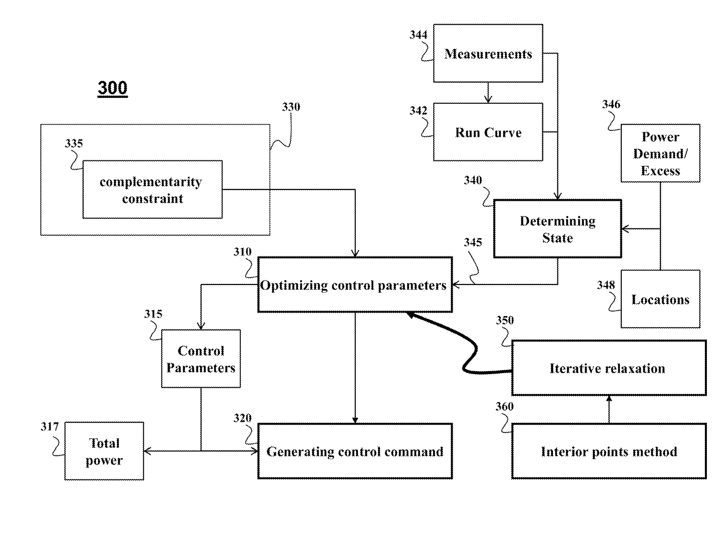
This patent is about a method to optimize the energy efficiency of a railway system by reducing the energy consumption of individual trains and the overall system. The method uses complementarity constraints to determine the control parameters for elevated voltage in power regenerating trains. The control parameters are optimized to reduce power surges and improve safety in the railway system. The method takes into account the impact of power generated by regenerative braking and the loss of regenerative power. The solution is achieved using iterative relaxation of the complementarity constraint and non-linear optimization methods, such as the interior point method. The global optimization approach results in a more accurate solution and reduced computational time.

Problems solved by technology

Also, if the railway system does not consume all the regenerative power, potentially damaging power surges can occur.
However, the optimization of control parameters controlling at least part of the energy consumption of the railway system has to be performed subject to constraints on various components of the railway system.
The constraints of the railway system can include discontinuities, which makes the optimization problem ill-posed.
However, due to the limitation on a feasibility region defined by the complementarity constraints, some non-linear optimization methods solve complementarity constraint problem with unacceptably high error rate.
This embodiment is based on a realization that relaxation of the complementary constraints results in inequality constraints, which is a difficult optimization problem.

Method used


Image

  • System and method for optimizing energy consumption in railway systems
  • System and method for optimizing energy consumption in railway systems
  • System and method for optimizing energy consumption in railway systems

Examples


Embodiment Construction

[0031]Railway System

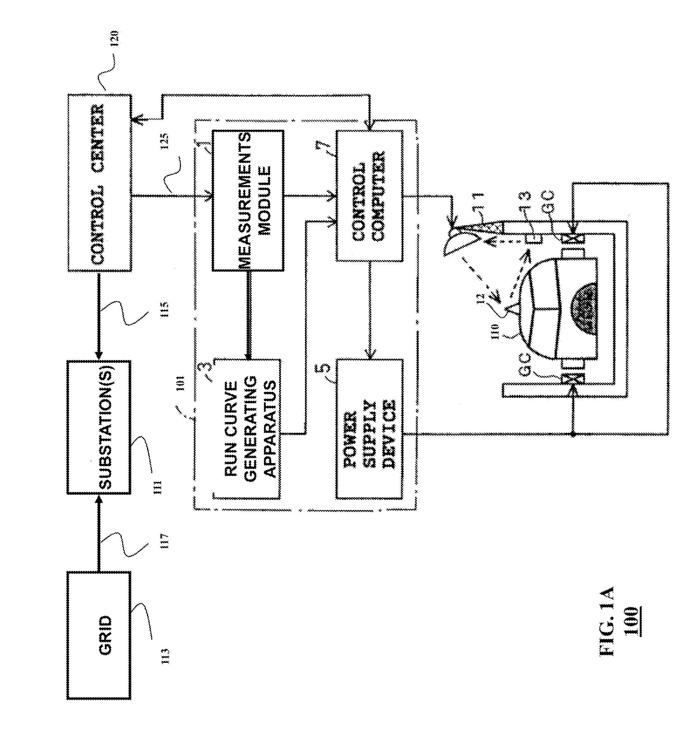
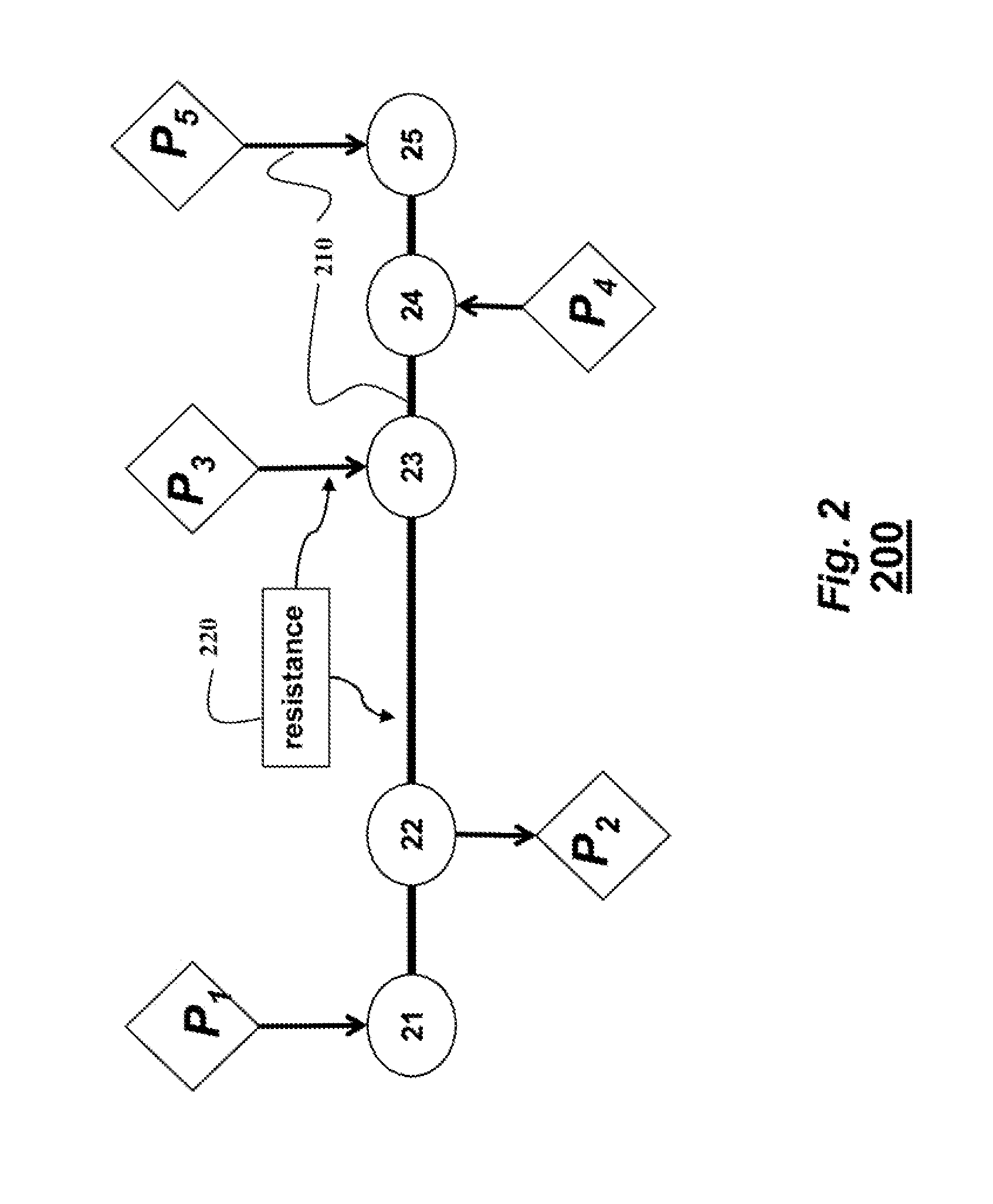
[0032]The embodiments of the invention optimize an energy consumption of a railway system that includes a set of trains and a set of substations. The substations are connected to a grid and provide power to the set of trains. Optimizing energy consumption includes minimizing the amount of power supplied to the railway system from the grid. The embodiments can reflect, in real-time, dynamically varying, states of the railway system, in terms of locations and identifications of substation and trains, and measured electrical characteristics such voltages, currents, and resistances in power lines of DC network connecting the substations and trains.

[0033]FIG. 1 show a railway system 100 according to some embodiments of the invention. The railway system 100 includes a set of trains, such as a train 110 and a set of substations 111. The train 110 can be an electrical train, wherein the electric power is converted and supplied to feeders or ground coils (GC) via breakers...


PUM


Abstract

A method optimizes energy consumption in a railway system including a set of trains and a set of substations connected to a grid. The method optimizes control parameters controlling at least part of the energy consumption of the railway system to produce optimized control parameters minimizing a total power provided by the grid to satisfy a power demand of the railway system. The optimizing is subject to constraints on operations of the railway system, which include as complementarily constraint. Next, the method generates a command to control the energy consumption of the railway system based on the optimized control parameters.

Description

FIELD OF THE INVENTION[0001]This invention relates generally to railway systems, and more particularly to optimizing energy consumption in railway systems.BACKGROUND OF THE INVENTION[0002]It is desired to reduce energy consumption in railway systems. Several methods are known that reduce energy during an operation of the railway systems. However, the conventional methods generally use static models, or only consider energy efficiency of the individual trains. For example, various run curve optimization methods can reduce energy consumption of the train. Regenerative braking can provide additional energy for the train. Although the conventional methods can increase energy efficiency, those methods do not consider global optimization of the operation of the railway system, and do not minimize total energy consumption.[0003]For example, U.S. 20050000386 describes a railway car drive system for accelerating and deaccelerating a train by operating a driving motor, and to improve the powe...

Claims


Application Information

Patent Timeline
IPC IPC(8): G06F17/11B61L99/00B60L11/18B60L9/04G06Q50/06G06Q50/00
CPCB60L11/1842G06Q50/06B60L15/2045B60L2200/26B60L9/04G06F17/11B61L99/00B60L9/00B61L27/0027B61L3/006B61L3/008Y02T10/7283Y02T10/72B61L27/16B61L15/0058B61L15/0062B60L55/00
Inventor RAGHUNATHAN, ARVIND UWADA, TOSHIHIROUEDA, KENJITAKAHASHI, SATORU
Owner MITSUBISHI ELECTRIC CORP
Learn More