Lath furring strip

a technology of lath furring and lath furring, which is applied in the direction of covering/linings, walls, ceilings, etc., can solve the problems of reducing the waterproofing features of the moisture barrier, transferring water to more expensive and structurally important components of the building, and the current lath furring strip, etc., to and reduce the height of the mounting leg

Active Publication Date: 2014-09-16
RUTHERFORD ROBERT B
View PDF21 Cites 2 Cited by
  • Summary
  • Abstract
  • Description
  • Claims
  • Application Information

AI Technical Summary

Benefits of technology

[0007]It is a purpose of the present invention to provide a low-profile lath furring strip that is more water resistant than currently available lath furring strips. The furring strip can be mounted onto the sheathing, framing or studding with a water resistive backing to reduce water seepage from the plaster to the wall, while maintaining a low height profile for proper plaster coating wall construction.
[0019]In another embodiment, the terminal end of the second mounting plate that includes an angled leg that crosses the plane of the first mounting plate. The angled leg is substantially at a 90 degree angle from the second mounting plate and extends beyond the mounting leg. This angled leg has an additional bend that is substantially parallel to both the first and second mounting plates, which creates a termination stop. The two mounting plates provide an additional layer of furring material between the lath and the wall or sheathing. A screw, nail, or other mounting device secures the lath furring strip termination stop to the wall. Preferably, a moisture barrier, such as building paper is placed on top of the first mounting plate of the furring strip closest to the lath, and covers the mounting device such that water cannot enter the a hole created by the mounting device into the wall or sheathing. The moisture barrier preferably has an adhesive that secures the moisture barrier to the top of first mounting plate nearest the mounting leg to prevent any water from the lath to get in between the moisture barrier and the hole created by the mounting device. The maximum height from the back of the second mounting plate to the top of the mounting leg, which attaches the lath, is 0.365 inches, and to reduce the height of this mounting leg, embodiments that reduce the height of the mounting leg, such as the ones previously described, may be employed. The termination stop furring strip preferably has a total profile height of ⅞ of an inch from the mounting plate against the wall to the end of the termination stop leg.

Problems solved by technology

In wall construction, plaster is generally applied to a flexible lath material instead of directly attaching the lath to a rigid structure, such as sheathing, because the current means of attaching a lath directly to a rigid structure can cause cracks.
This penetration creates holes which diminish the waterproofing features of the moisture barrier.
Since plaster is water absorbent, it can transmit water to more expensive and structurally important components of the building, such as the sheathing or the framing.
However, there are still problems with current lath furring strips.
A problem with adding additional waterproofing layers to the furring strip is that any additional waterproofing on the furring strip would increase the profile height of the lath furring strip.
However, one drawback of using a lath furring strip with a profile of less than ⅜ of an inch is that it may reduce the attachment strength on the furring strip where the lath is secured.
Although one might consider reducing the side of the attachment hole on the mounting leg, it takes skill insert wire ties through a lath and attachment hole, and reducing the size of the hole to leave more metal in between the attachment hole and the edge of the mounting leg would make it much more difficult for the practitioner to secure the lath to the mounting leg.

Method used


Image

  • Lath furring strip
  • Lath furring strip
  • Lath furring strip

Examples


Embodiment Construction

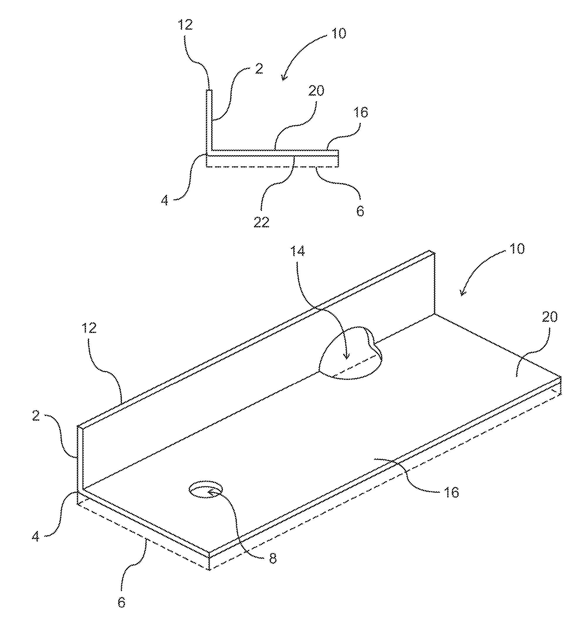
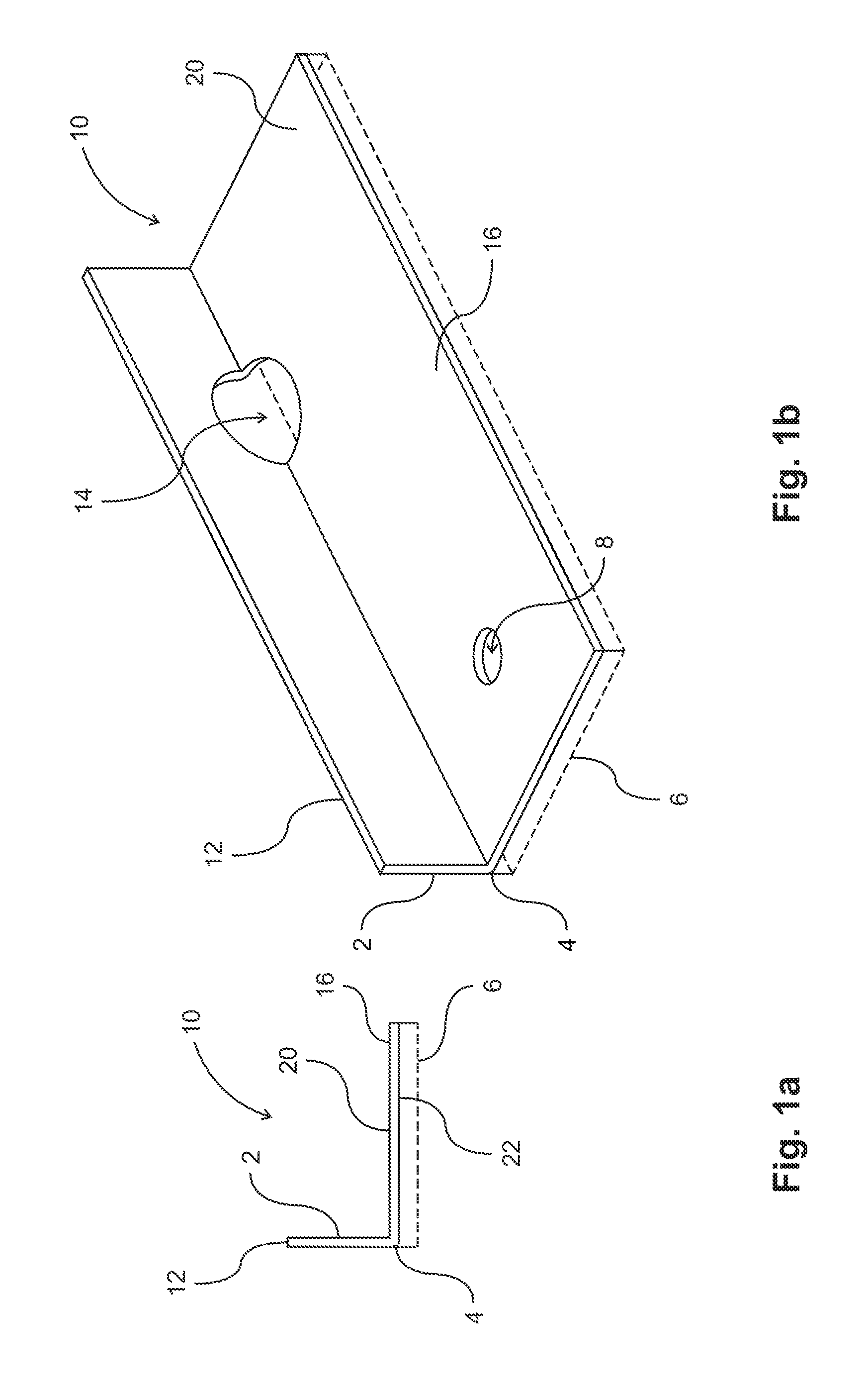
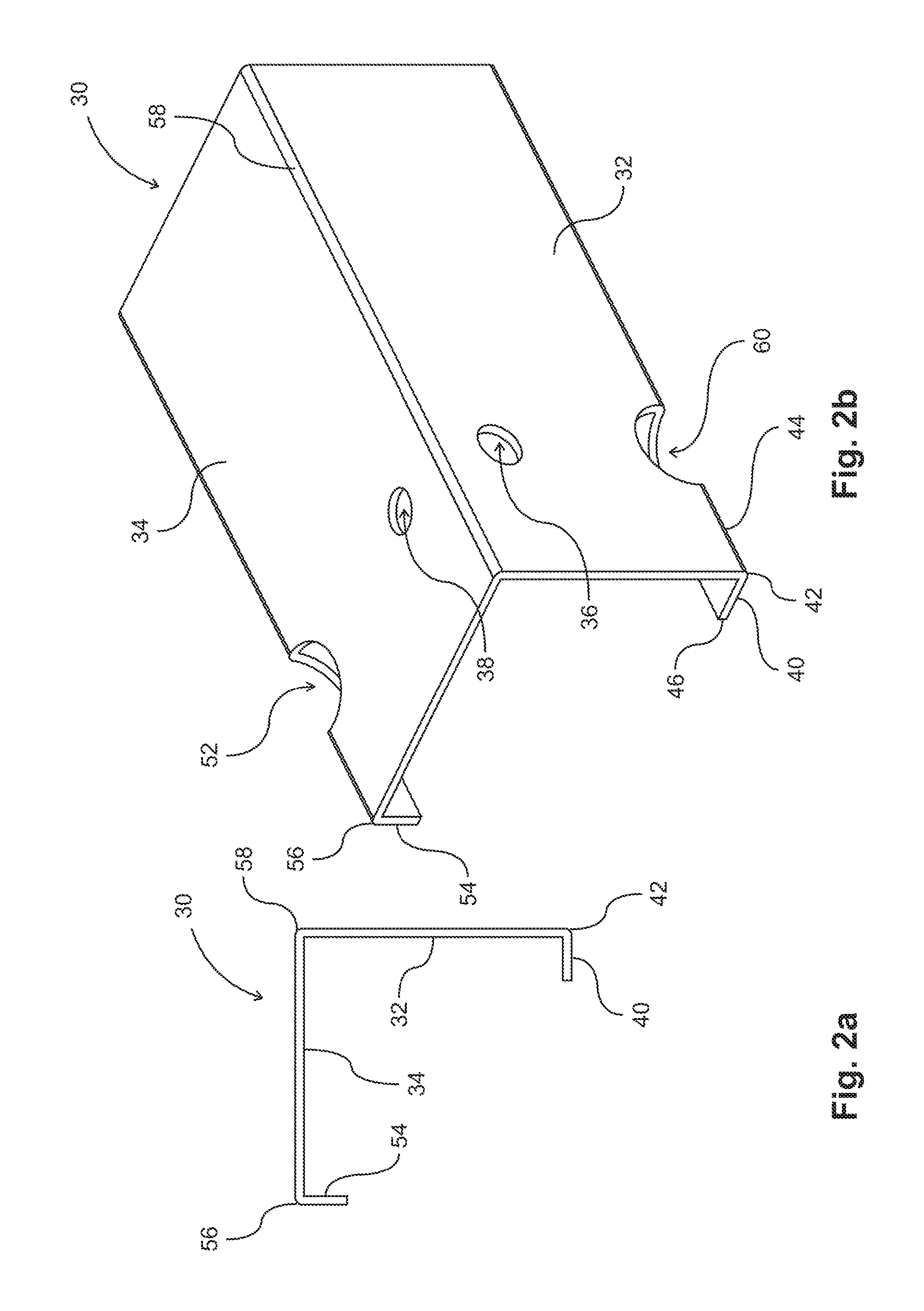
[0044]The following description is of the best-contemplated mode of carrying out the invention. This description is made for the purpose of illustrating the general principles of the invention and should not be taken in a limiting sense. The scope of the invention is best determined by reference to the appended claims. Preferable embodiments of the present invention are described with reference to the FIGS. 1-11. FIG. 1, FIG. 5, and FIG. 6 show various embodiments of increasing the waterproofing characteristics of the lath furring strip. FIG. 2, FIG. 3, and FIG. 4 show various embodiments of the shape of the lath furring strip without any waterproofing elements, but can incorporate the waterproofing elements of the embodiments in any other figure. FIG. 7 and FIG. 8 show various embodiments of how the lath furring strip and lath are assembled, and may incorporate any of the waterproofing or lath shapes in any of other figures. FIG. 9, FIG. 10, and FIG. 11 show various embodiments of ...


PUM


Abstract

The present invention provides a lath furring strip having a height not exceeding 0.365 inches which has a flexible elastic water resistive barrier (e.g. rubber) to minimize water seepage from the plaster on the lath to a structure behind the lath furring strip and a hemmed mounting leg to increase the strength of the mounting leg near the lath attachment hole. By incorporating a flexible elastic water resistive barrier into the lath furring strip, when the flexible elastic waterproof barrier on the lath furring strip is squeezed by the force of a screw or nail that secures the lath furring strip to a sheathing or moisture barrier (such as building paper), any holes in the sheathing or moisture barrier which might have allowed water to seep from the plaster to the sheathing will be sealed due to the properties of the flexible elastic water resistive barrier covering those holes.

Description

FIELD OF THE INVENTION[0001]This invention relates to lath furring strips. In particular, this invention relates to a low-profile lath furring strip with improved water resistance.BACKGROUND OF THE INVENTION[0002]The present invention is directed to overcoming problems associated with securing a lath to a sheathing (or a wall structure). In wall construction, plaster is generally applied to a flexible lath material instead of directly attaching the lath to a rigid structure, such as sheathing, because the current means of attaching a lath directly to a rigid structure can cause cracks. By applying plaster to a metal lath (which include structures such as welded wire, woven wire, and expanded metal lath), the plaster cracks less frequently than if compared to applying the plaster directly to the sheathing. The current method of fastening laths to sheathing is either with staples, nails or screws. Although a moisture barrier, such as building paper, can be placed between the lath and ...

Claims


Application Information

Patent Timeline
Patent Type & Authority Patents(United States)
IPC IPC(8): E04B1/64
CPCE04F13/06
Inventor RUTHERFORD, ROBERT, B.
Owner RUTHERFORD ROBERT B
Why Eureka
Try Eureka