Cover plate, door covering and aircraft or spacecraft

a technology for applied in the field of cover plates, door coverings and aircraft or spacecraft, can solve the problems of cover plate vibration, noise, and insufficient contact between the cover plate and the fuselage cell, and achieve the effects of preventing vibration, constant contact pressure, and reliably preventing the core corrosion

Inactive Publication Date: 2014-09-16
AIRBUS OPERATIONS GMBH
View PDF10 Cites 6 Cited by
  • Summary
  • Abstract
  • Description
  • Claims
  • Application Information

AI Technical Summary

Benefits of technology

[0007]The fundamental idea of the present invention is for the contact pressure, by which the contact portion of the cover plate is pressed against the outer skin of the fuselage cell, to be kept constant over the entire region of the contact portion. This measure prevents the contact portion from being pressed against the outer skin of the fuselage cell with an insufficient contact pressure in parts of the contact portion which are susceptible to vibrations and consequently from being able to lift away from said outer skin during flight operation. This reliably prevents the development of vibrations and hence a disturbing development of noise.
[0008]According to a preferred embodiment of the cover plate, the at least one corner portion has a first precurvature directed towards the outer skin of the fuselage cell and the side portion has a second precurvature directed towards the outer skin of the fuselage cell, the second precurvature being greater than the first precurvature. Preferably, the at least one corner portion has a first rigidity and the side portion has a second rigidity, the second rigidity being greater than the first rigidity. This means that a greater pretension is produced in the region of the side portion than in the region of the at least one corner portion. Consequently, with simple constructive means, it is possible to achieve a constant contact pressure over the entire contact portion of the cover plate.
[0009]According to a further preferred embodiment of the cover plate, the cover plate comprises a core which is arranged between two skin layers of the cover plate. The core is formed in particular from a metal material, for example from a curved sheet. The skin layers preferably comprise a plastics material, in particular a fibre-reinforced plastics material. This reliably prevents corrosion of the core, thereby prolonging the service life of the cover plate. Furthermore, a high surface quality of the cover plate is achieved due to the skin layers.
[0010]According to yet another preferred embodiment of the cover plate, the core comprises a plurality of core elements. In particular, the core elements each have different first or second precurvatures directed towards the outer skin of the fuselage cell and / or different rigidities in each case. Thus, in a particularly simple manner, it is possible to provide a core having the desired characteristics, i.e. having the desired first and second precurvatures and the required rigidities, by assembling different standardised core elements. As a result, the core can be produced in a particularly simple and cost-effective manner.
[0011]According to a preferred embodiment of the door covering, the cover plate is mounted on an upper edge of the door covering. This prevents the development of noise, particularly in the region of the upper edge.

Problems solved by technology

However, aircraft fitted with cover plates of this type might develop a considerable amount of noise.
This noise development is due to the fact that the touching contact between the cover plate and the fuselage cell is not fully maintained during flight operation.
This means that the cover plate lifts away at least in portions from the fuselage cell, as a result of which the cover plate starts to vibrate and produces a noise.
However, a renewed resetting operation of this type might involve increased costs and time since the aircraft then has to undergo new flight tests.
Furthermore, it has been found that the development of vibrations on the cover plates might not be reliably prevented even if the door coverings are reset.

Method used


Image

  • Cover plate, door covering and aircraft or spacecraft
  • Cover plate, door covering and aircraft or spacecraft
  • Cover plate, door covering and aircraft or spacecraft

Examples


Embodiment Construction

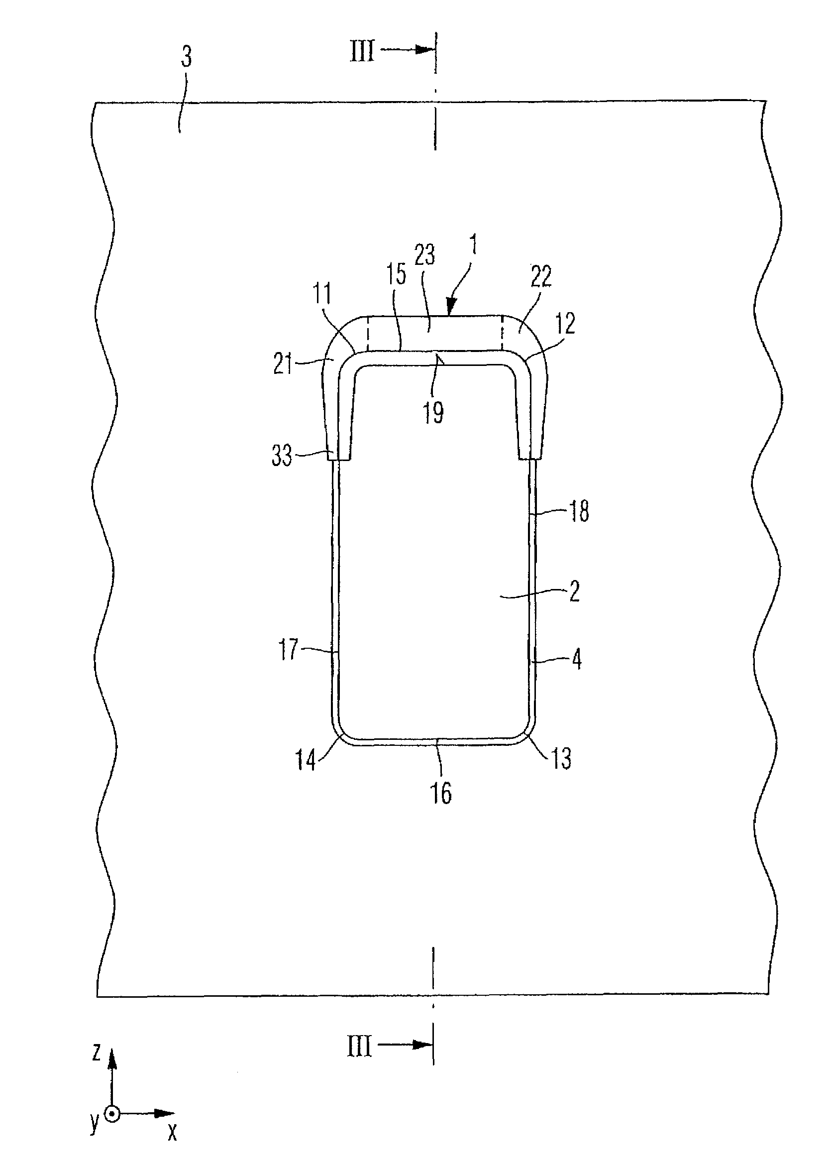
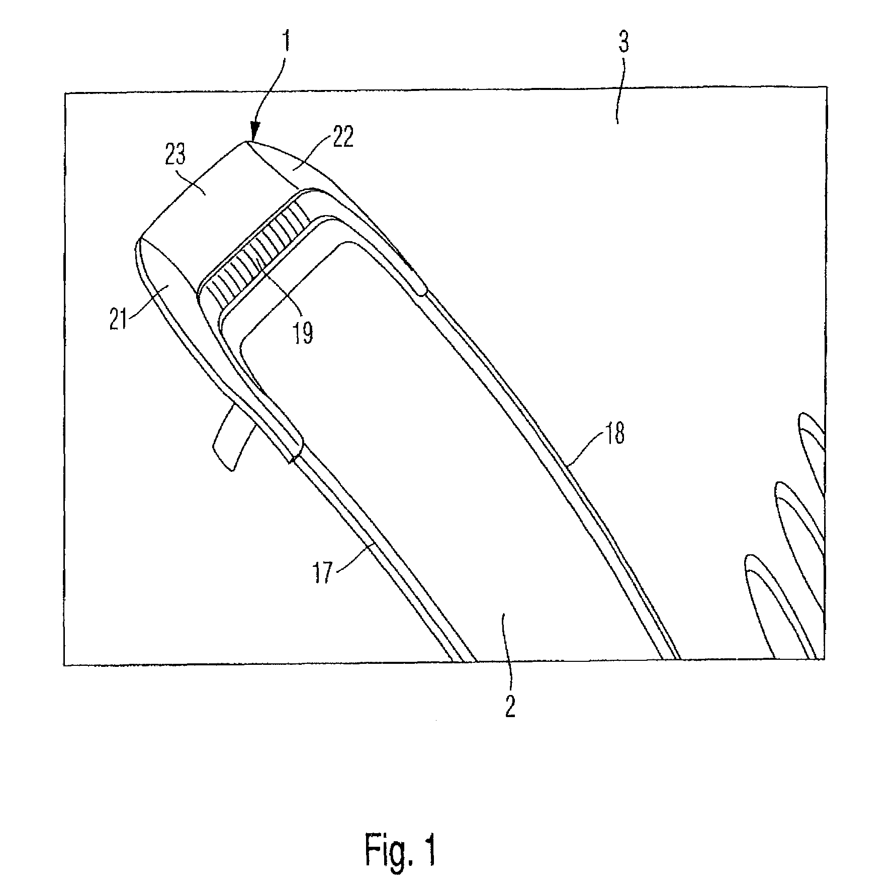
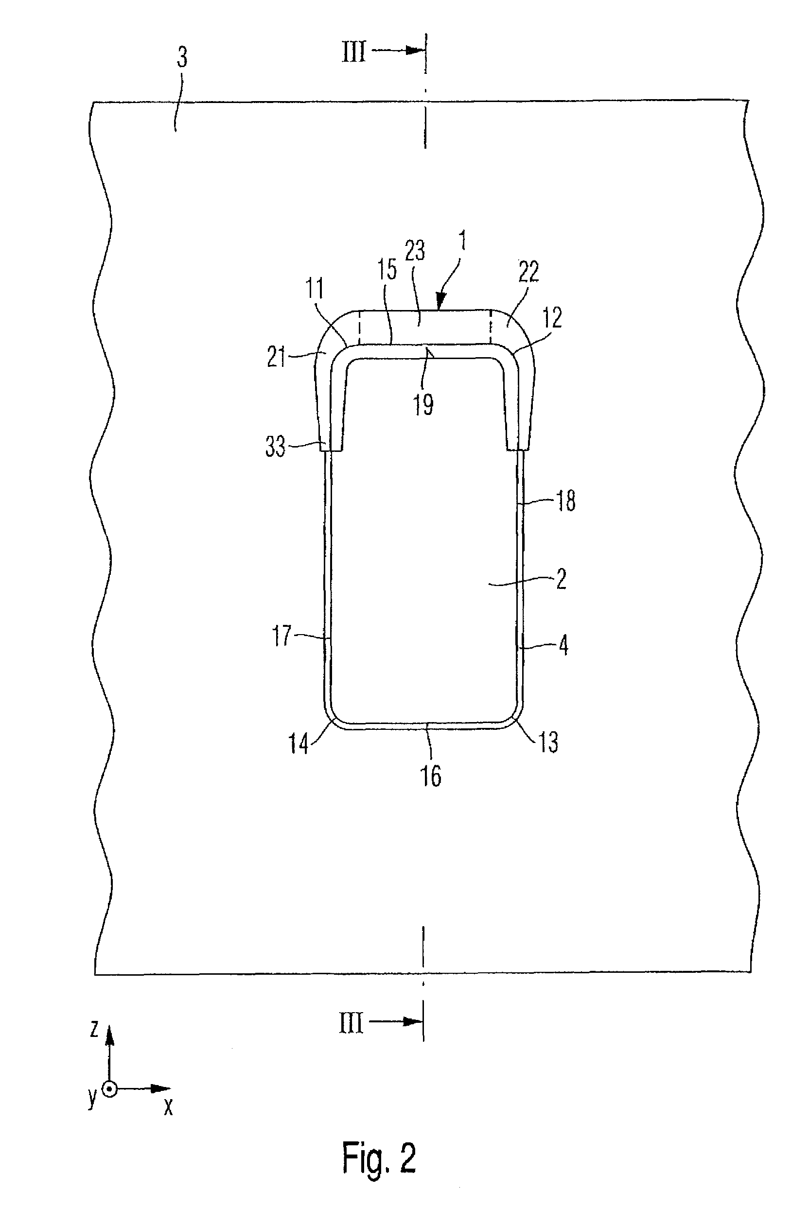
[0023]FIGS. 1 to 4, to which reference will be made simultaneously, illustrate a preferred embodiment of a cover plate 1 for covering a door gap 4 formed between a door covering 2 and a fuselage cell 3 of an aircraft or spacecraft. The cover plate 1 is preferably configured as a so-called cover plate 1.

[0024]The fuselage cell 3 preferably has an access opening 5 which can be closed by the door covering 2. The door covering 2 is also known as the door leaf 2. Passengers or any loads, for example, can pass into the fuselage cell 3 through the open access opening 5. The door covering 2 is preferably mounted on the fuselage cell 3 such that it can swivel thereon by a hinge means. The door gap 4 is formed between the door covering 2 and the access opening 5. The door gap 4 can run round the entire door covering 2. The door gap 4 is preferably only formed on an outer skin 6 of the fuselage cell 3, in other words the door gap 4 preferably does not form a connection between the exterior 7 a...


PUM


Abstract

The present invention provides a cover plate for covering at least portions of a door gap formed between a door covering and a fuselage cell of an aircraft or spacecraft, comprising: a fastening portion by which the cover plate can be mounted on an outer surface of the door covering; a contact portion which rests in a contacting manner against an outer skin of the fuselage cell when the door covering is closed; at least one corner portion associated with a corner of the door covering; and a side portion associated with a side of the door covering, the at least one corner portion and the side portion being configured to press the contact portion with a constant contact pressure against the outer skin of the fuselage cell when the door covering is closed. The present invention further provides a door covering for an access opening in a fuselage cell of an aircraft or spacecraft having a cover plate of this type as well as an aircraft or spacecraft having a cover plate of this type and / or having a door covering of this type.

Description

CROSS-REFERENCE TO RELATED APPLICATIONS[0001]This application claims the benefit of and priority to U.S. Provisional Application No. 61 / 552,207, filed Oct. 27, 2011, and German Patent Application No. DE 10 2011 085 269.7, filed Oct. 27, 2011, the entire disclosures of which are incorporated herein by reference.FIELD OF THE INVENTION[0002]The present invention relates to a cover plate for covering a door gap formed between a door covering and a fuselage cell of an aircraft or spacecraft, to a door covering for an access opening in a fuselage cell of an aircraft or spacecraft having a cover plate of this type and to an aircraft or spacecraft having a cover plate of this type and / or having a door covering of this type.[0003]Although the present invention can be applied to any aircraft or spacecraft, it will be described by way of example on the basis of an aircraft.BACKGROUND OF THE INVENTION[0004]In aircraft construction, cover plates are used to cover a door gap which is formed betwe...

Claims


Application Information

Patent Timeline
Patent Type & Authority Patents(United States)
IPC IPC(8): B64C1/14
CPCB64C1/1407
Inventor KLAAS, ANDREJSTOHL, MICHAELHINRICHS, ROLF
Owner AIRBUS OPERATIONS GMBH
Why Eureka
Try Eureka