Vehicle glazing

a technology for vehicles and backlights, applied in the field of vehicles, can solve the problems of increasing complexity, difficult to fix a flat substrate to a surface of the backlight, and complex shape of the vehicle backlight, and achieve the effect of increasing the number of opportunities

Active Publication Date: 2014-09-16
PILKINGTON GROUP LTD
View PDF33 Cites 9 Cited by
  • Summary
  • Abstract
  • Description
  • Claims
  • Application Information

AI Technical Summary

Benefits of technology

[0008]The present inventor has, with the invention to be described herein, made technical advances regarding vehicle glazings which incorporate a light emitting diode device, and has thereby increased the number of opportunities for exploiting the benefits of a glazing incorporating a light emitting diode device. In one particular aspect, the present inventor has devised a novel backlight incorporating an auxiliary stop lamp (comprising a light emitting diode device) which does not suffer from the problems that are associated with the glazings presently known.

Problems solved by technology

Vehicle backlights may be complex in shape (and currently there is a growing trend towards greater complexity).
A backlight may have curvature in two or more directions which may make it difficult to fix a flat substrate to a surface of the backlight.
Although the stop lamp in EP '615 is described as being made from a flexible substrate, the thickness of the substrate may in fact impair its flexibility, especially if the stop lamp were to be arranged on a backlight having complex curvature, to which the substrate would need to conform.
Stress introduced into the substrate as it is bent to such a curvature would be likely to weaken the adhesion of the substrate to the glazing, resulting in an imperfect vehicle glazing in need of repair.
A further problem with the stop lamp described in EP '615 results from the size of the openings in the substrate; the stop lamp will typically have a relatively large overall surface area (as compared to conventional high mounted stop lamps) in order to accommodate enough light emitting diode chips for the stop lamp to function effectively (for example, to be bright enough for drivers of other vehicles to see).
Despite the presence of openings in the substrate however, such a “large” stop lamp would nonetheless obtrude the rear-view vision of the driver of a vehicle which incorporates said stop lamp on its backlight.
However, until now, light emitting diode devices have only been used as part of an auxiliary stop lamp attached to a backlight (this being the only lamp where it has been considered, and where it has subsequently been possible, to replace conventionally used incandescent light bulbs with light emitting diodes), or laminated in a windscreen where they function as indicia.

Method used


Image

  • Vehicle glazing
  • Vehicle glazing
  • Vehicle glazing

Examples


Embodiment Construction

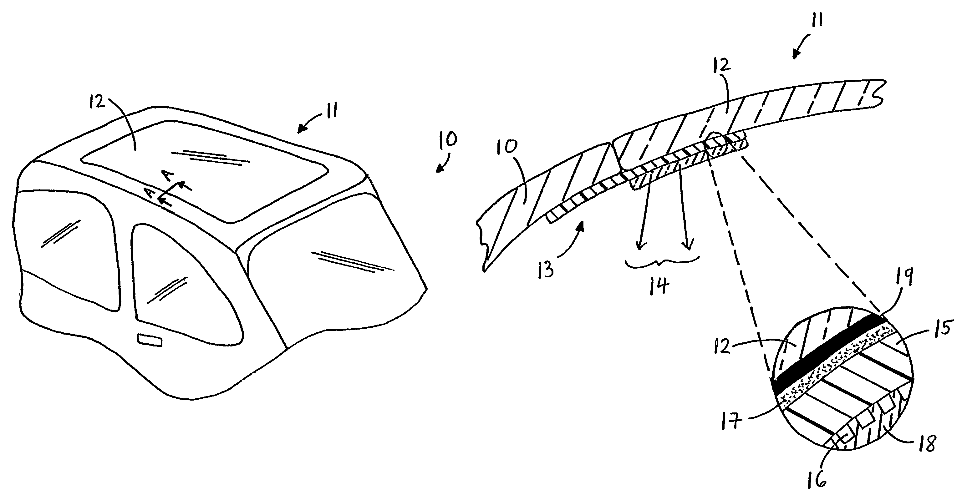
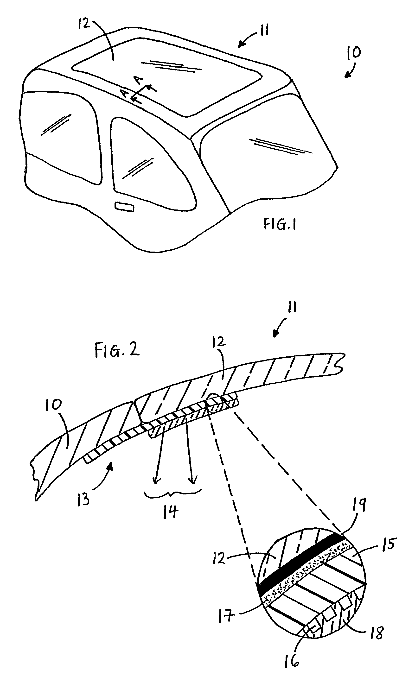
[0054]Vehicle 10 shown in FIG. 1 has a rooflight 11 which comprises pane of glazing material in the form of a pane of glass 12. Rooflight 11 is an exemplary first embodiment of a vehicle glazing according to the first aspect of the present invention. It is shown in more detail in FIG. 2, which illustrates the relative position of vehicle body 10 and rooflight 11. To pane of glass 12 (which is comprised in rooflight 11) light emitting diode device 13, in the form of an illuminator which provides for example courtesy lighting, is attached. Arrows labelled 14 indicate that light is emitted from light emitting diode device 13 into the vehicle of FIG. 1.

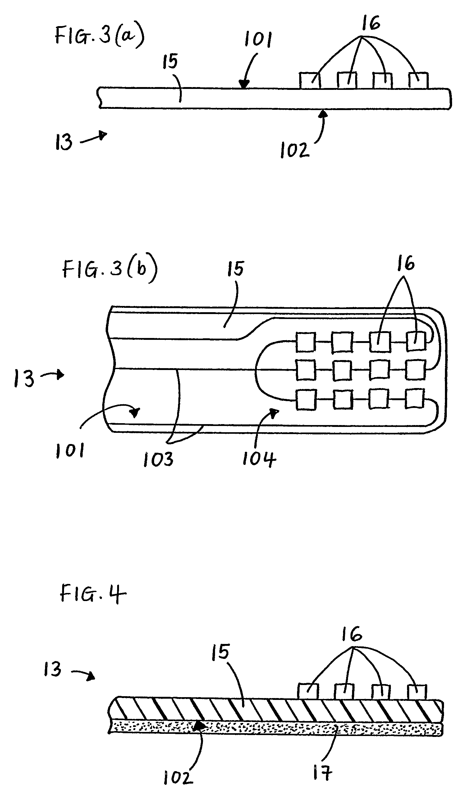
[0055]The magnified section of FIG. 2 shows that light emitting diode device 13 comprises substrate 15, in the form of a flexible circuit board, on which a number of light emitting diodes 16 are mounted, and which are covered by layer of transparent encapsulant 18, for example an epoxy resin, acrylate, methacrylate or silicone, none of wh...


PUM


Abstract

A vehicle glazing comprising a pane of glazing material having an exposed surface and a light emitting diode device
  • a) other than an auxiliary stop lamp adhesively attached to the exposed surface of the pane of glazing material, or
  • b) in the form of an auxiliary stop lamp adhesively attached to the exposed surface of the pane of glazing material, the lamp comprising a substrate having a functional surface on which a plurality of light emitting diodes is provided, and which is provided with a layer of transparent encapsulant to cover the light emitting diodes
is disclosed. A process for the production of such a vehicle glazing comprising applying adhesive to a surface of the vehicle glazing, positioning the light emitting diode device with respect to the pane of glazing material and activating the adhesive is also disclosed.

Description

FIELD OF THE INVENTION[0001]The present invention relates to a vehicle glazing which incorporates at least one light emitting diode, more particularly to an automotive vehicle glazing incorporating a light emitting diode device, and to a process for the production of such a vehicle glazing.DESCRIPTION OF RELATED ART[0002]A vehicle backlight (a rearward facing window in a vehicle) comprising a single pane of glass and an auxiliary stop lamp, which includes one or more light emitting diodes in its construction, mounted on one of the surfaces of the pane of glass is known. European patent application EP 1 277 615 A1 describes an auxiliary stop lamp (also known as a “high mounted stop lamp” or “third brake light”) which is arranged on the inner surface of a vehicle rear-window glazing panel. The stop lamp comprises a flexible substrate (of a thickness between 0.2 and 0.9 mm) provided with a plurality of 10 mm square openings (purportedly to increase driver visibility in the region of th...

Claims


Application Information

Patent Timeline
Patent Type & Authority Patents(United States)
IPC IPC(8): B60Q1/26B60Q3/00B60Q1/30B60Q3/02
CPCB60Q1/302B60Q1/2696B60Q1/268B60Q3/0213B60Q1/44B60Q3/208F21Y2115/10
Inventor BARTON, NEILDAY, STEPHEN ROLAND
Owner PILKINGTON GROUP LTD
Why Eureka
Try Eureka