Lighting devices with patterned printing of diffractive extraction features

a technology of diffractive extraction and lighting devices, which is applied in the direction of lighting and heating apparatus, planar/plate-like light guides, instruments, etc., can solve the problem that indicia can become readily apparent to users of lighting devices, and achieve the effect of low distortion and difficult copying or counterfeiting

Inactive Publication Date: 2014-09-16
3M INNOVATIVE PROPERTIES CO
View PDF66 Cites 22 Cited by
  • Summary
  • Abstract
  • Description
  • Claims
  • Application Information

AI Technical Summary

Benefits of technology

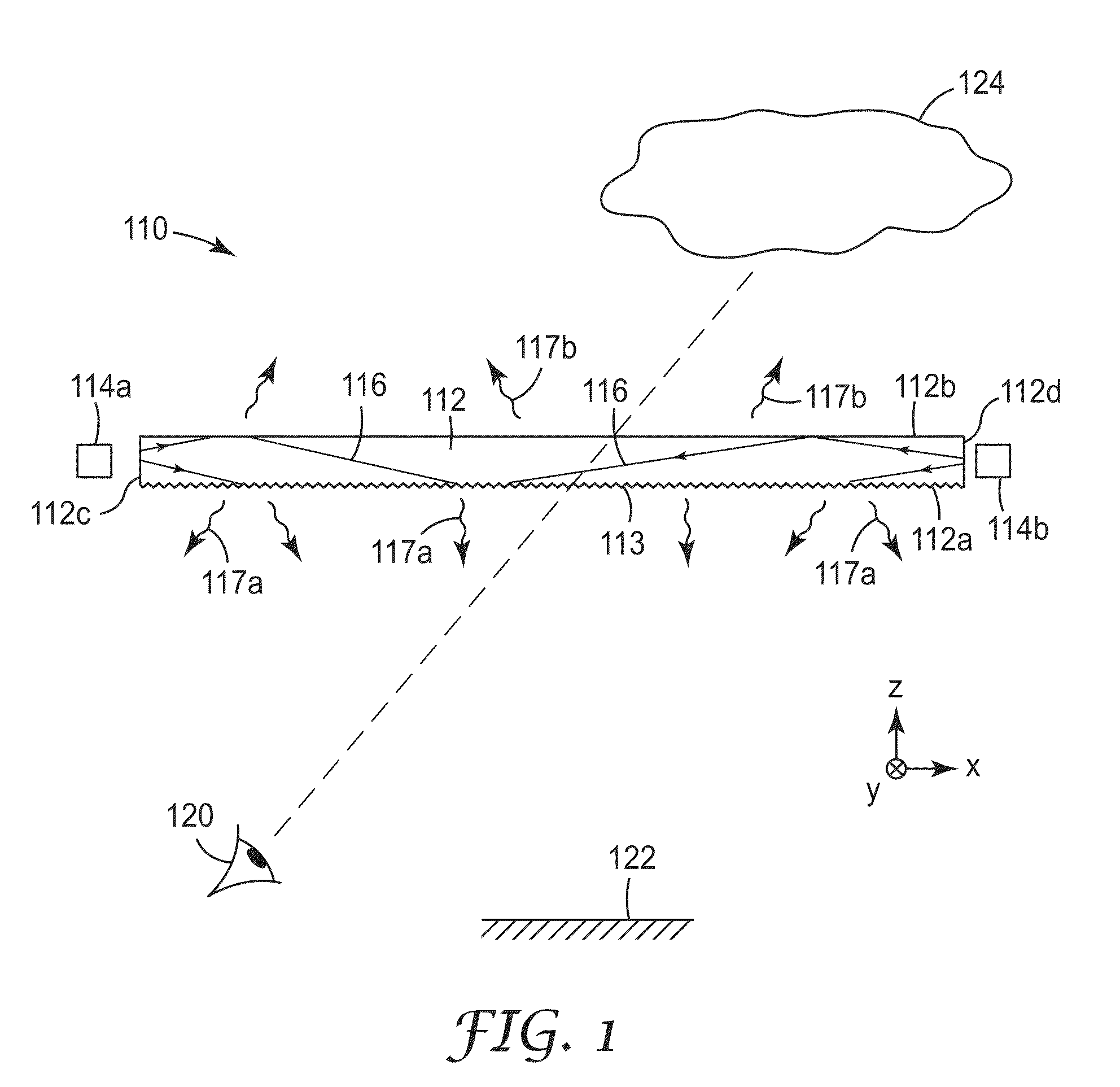
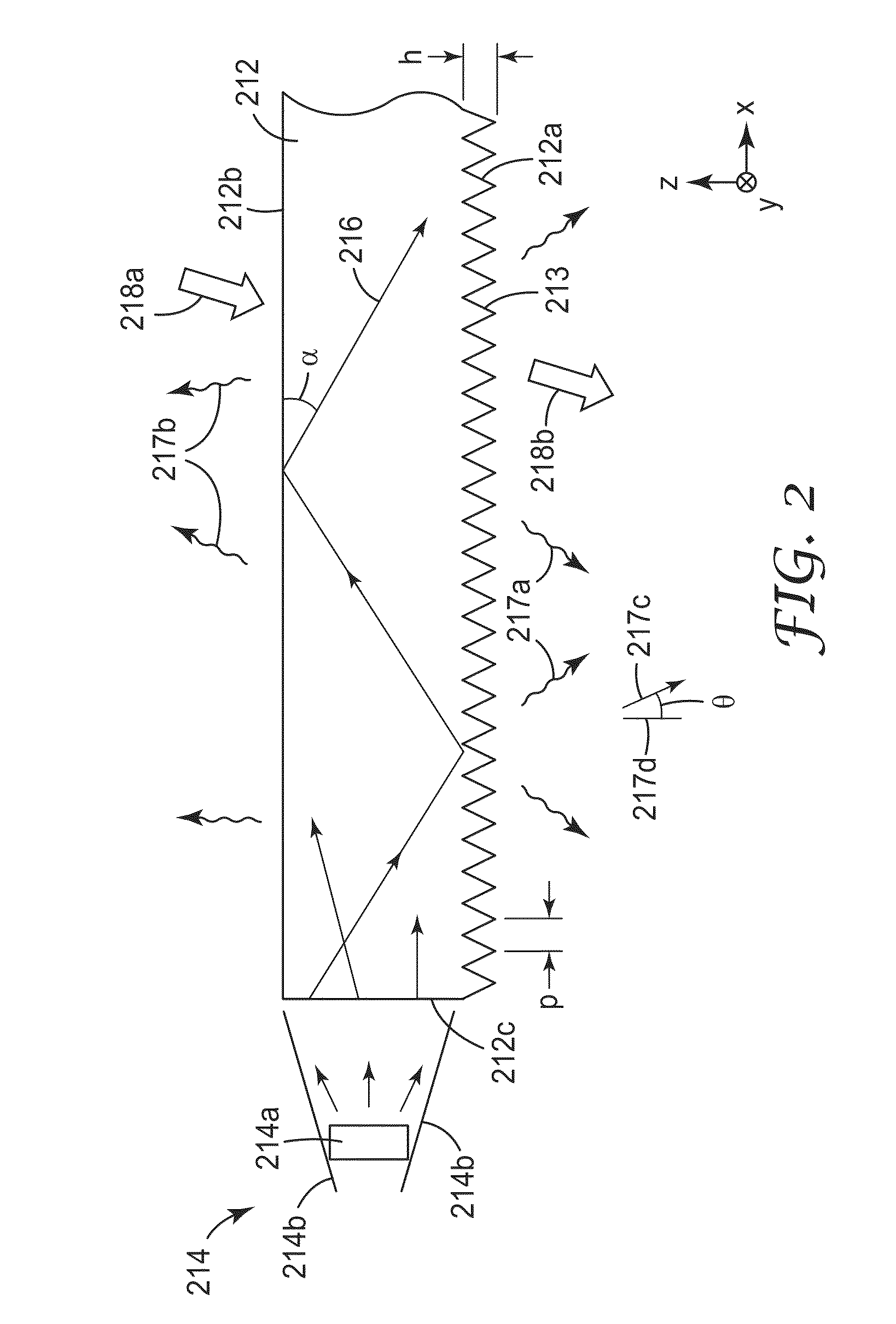
[0007]The first and second refractive indices may differ by at least 0.05, or by at least 0.1. The first and second portions of the first major surface may define indicia. The first and second refractive indices may be sufficiently different so that differences in out-coupled light between the first and second portions cause the indicia to be readily apparent to a user of the lighting device when guided-mode light propagates within the light guide. The light guide may exhibit low distortion for viewing objects through the light guide in both the first and second portions. The indicia may not be readily apparent to a user of the lighting device when guided-mode light does not propagate within the light guide.
[0012]The optical film may exhibit low distortion for viewing objects through the optical film in both the first and second portions. The first and second portions of the first major surface may define indicia. The indicia may not be readily apparent to a user of the film before the film is attached to the substrate.
[0014]The disclosed lighting devices may also be adapted for use as security articles, e.g., articles intended for application to a product, package, or document as an indicator of authenticity, because the visual features are difficult to copy or counterfeit. Such articles thus preferably include a light guide and a patterned light transmissive layer. The light guide has a first major surface. First and second diffractive surface features are formed in respective first and second portions of the first major surface, and at least one of the first and second diffractive surface features are adapted to couple guided-mode light out of the light guide. The patterned light transmissive layer, which includes a second light transmissive medium, is in optical contact with the second diffractive surface features but not the first diffractive surface features. The lighting device also includes a first light transmissive medium in optical contact with the first diffractive surface features but not the second diffractive surface features. The first and second light transmissive media may have different first and second refractive indices respectively at a visible wavelength. The light guide may exhibit low distortion for viewing objects through the light guide in both the first and second portions.

Problems solved by technology

However, when the light sources are turned on or energized to provide the guided-mode light, the indicia can become readily apparent to users of the lighting device.

Method used


Image

  • Lighting devices with patterned printing of diffractive extraction features
  • Lighting devices with patterned printing of diffractive extraction features
  • Lighting devices with patterned printing of diffractive extraction features

Examples


example 1

[0130]A lighting device suitable for use as a luminaire was made and evaluated. The device incorporated a circular-shaped light guide with diffractive surface features in the form of a spiral pattern, the diffractive surface features arranged into repeating patterns of six packet types with different groove or prism pitches. A mounting ring was used to position thirty-six equally spaced LEDs around the curved side surface of the light guide to inject light into the light guide. Indicia in the shape of a United States map was formed by patterned printing on the diffractive surface features. Further details of construction will now be given.

[0131]A precision diamond turning machine was used to cut a spiral-shaped groove pattern, which became the diffractive surface features in the lighting device after replication, into the copper surface of a cylindrical tool. The diamond was shaped so that the grooves had a sawtooth (asymmetric) profile in cross section similar to FIG. 6, with a hei...

example 2

[0138]Another lighting device suitable for use as a luminaire was made and evaluated. The device incorporated a circular-shaped light guide with diffractive surface features. The diffractive surface features filled 36 triangle-shaped areas which were uniformly sized and tiled to substantially fill the circular area of the light guide. The diffractive surface features in each of the triangle-shaped areas were straight and parallel to each other, and of a single pitch, although three different triangle types of three different pitches were used. A mounting ring was used to position thirty-six equally spaced LEDs around the curved side surface of the light guide to inject light into the light guide. Indicia in the shape of a United States map was formed by patterned printing on the diffractive surface features. Further details of construction will now be given.

[0139]A precision diamond turning machine was used to cut linear grooves into the copper surface of a cylindrical tool. The dia...

example 3

[0146]Another lighting device suitable for use as a luminaire was made and evaluated. The device incorporated a rectangular-shaped light guide with diffractive surface features. The diffractive surface features were a portion of the spiral-shaped groove pattern described in Example 1, the portion taken from a central rectangular region of the spiral pattern. A light source module was mounted along one of the short edges of the rectangular light guide, the light source module containing one row of eighteen equally spaced individual, discrete light sources, the light sources being nominally identical LEDs each emitting white light in a divergent distribution. The light guide also incorporated a patterned low index subsurface layer in the form of a random gradient dot pattern. The light guide was also capable of incorporating patterned printing, such as the United States map indicia or other desired indicia, in contact with the diffractive surface features. Further details of construct...


PUM


Abstract

Extended area lighting devices include a light guide and diffractive surface features on a major surface of the light guide, at least some diffractive surface features adapted to couple guided-mode light out of the light guide. The diffractive features include first and second diffractive features disposed on respective first and second portions of the major surface. A patterned light transmissive layer, including a second light transmissive medium, optically contacts the second diffractive features but not the first diffractive features. A first light transmissive medium optically contacts the first but not the second diffractive features. The first and second portions may define indicia, and the first and second diffractive features provide low distortion for viewing objects through the light guide such that the indicia is not readily apparent to users when guided-mode light does not propagate within the light guide. Optical films having such diffractive features are also disclosed.

Description

FIELD OF THE INVENTION[0001]This invention relates generally to lighting devices, with particular application to lighting devices that incorporate a light guide and diffractive elements to couple guided-mode light out of the light guide. The invention also relates to associated articles, systems, and methods.BACKGROUND[0002]Extended area lighting devices that use a light guide to spread light from discrete edge-mounted CCFL or LED light sources over the extended area of the light guide are known. Edge-lit backlights used in liquid crystal displays (LCDs) are a major example of such lighting devices. Ordinarily, it is important for such lighting devices to have a color and brightness that are uniform, or at least slowly varying, as a function of position on the extended area output surface. It is also ordinarily important for such lighting devices to emit light of a substantially white color, so that the filtering action of the liquid crystal panel can produce full color pixels and p...

Claims


Application Information

Patent Timeline
Patent Type & Authority Patents(United States)
IPC IPC(8): F21V8/00F21V7/04
CPCG02B6/005G02B6/006G02B6/0038G02B6/0036G02B5/1819F21V13/02G02B6/0035G02B6/0058
Inventor THOMPSON, DAVID S.YANG, ZHAOHUISTAY, MATTHEW S.JONES, VIVIAN W.
Owner 3M INNOVATIVE PROPERTIES CO
Why Eureka
Try Eureka