Controlling a motor of an injection device

a technology of injection device and control motor, which is applied in the direction of suction device, intravenous device, other medical devices, etc., can solve the problem of unoptimized energy efficiency and achieve the effect of reliable signal

Active Publication Date: 2014-09-16
SANOFI AVENTIS DEUT GMBH
View PDF5 Cites 0 Cited by
  • Summary
  • Abstract
  • Description
  • Claims
  • Application Information

AI Technical Summary

Benefits of technology

[0019]The invention proceeds from the consideration that the torque that has to be provided by the motor of an injection device depends on the force that is required to move a plunger in a cartridge. This force may depend for example on the backpressure of a liquid leaving the cartridge when the plunger is moved forward and on friction acting on the plunger. The force can be measured by means of a force sensor. Since the available torque at a motor depends primarily on the current that is applied to the motor, it is proposed to control the current that is applied to the motor depending on the measured force and thus on the currently required mechanical power. This may have the effect that only as much torque is made available as needed and taken off. As a result, less energy may be converted into heat and the power consumption of the injection device may be decreased. Certain embodiments of the proposed approach may thus enable an energy-efficient control of a motor. If the injection device draws power from a battery, the life-span of the battery may be lengthened.
[0020]Embodiments of the proposed approach may be seen as an alternative or supplement to the approach presented in document EP 0 481 376 A2. Compared to document EP 0 481 376 A2, certain embodiments of the proposed approach are moreover more flexible, since the operating cycle does not have to be split up into intervals which are mapped to marked rotation angles of the motor. Moreover, certain embodiments of the proposed approach are better suited to deal with variations between operating cycles. Certain embodiments of the proposed approach are furthermore suited to save more energy, since the provided current can be matched more closely to the actually required torque.
[0026]Providing always a slightly higher available torque at the output of the motor than currently required for moving the plunger may ensure a reliable movement of the plunger. For example, a possibly upcoming increase in the required mechanical power can be taken into account this way. The proposed increment by a fixed value and the proposed increment by a fixed fraction are examples that may be used to this end and that can be implemented in a particularly easy manner.
[0030]In another exemplary embodiment of the proposed method, the motor is configured to apply a force to the plunger by means of a piston rod, and the method further comprises measuring the force that is applied by the motor to the plunger by means of a force sensor that is either integrated in the piston rod or arranged between the piston rod and the plunger. In an exemplary embodiment of the proposed apparatus, the apparatus could further comprise the force sensor, the motor and a piston rod, the motor being configured to apply a force to the plunger by means of the piston rod, and the force sensor being configured to measure the force that is applied by the motor to the plunger, wherein the force sensor is either integrated in the piston rod or arranged between the piston rod and the plunger. These embodiments have the effect that in the case of exchangeable cartridges, it is not required to provide a new force sensor with each cartridge.
[0031]All of the proposed locations for the force sensor have the advantage that there is usually no relative movement between the plunger and an element interacting with the plunger. Thus, an implementation resulting in a reliable signal may in some cases be easier than with a force sensor arranged for instance between motor and transmission.

Problems solved by technology

As a result, the energy efficiency is not optimal.

Method used


Image

  • Controlling a motor of an injection device
  • Controlling a motor of an injection device
  • Controlling a motor of an injection device

Examples


Embodiment Construction

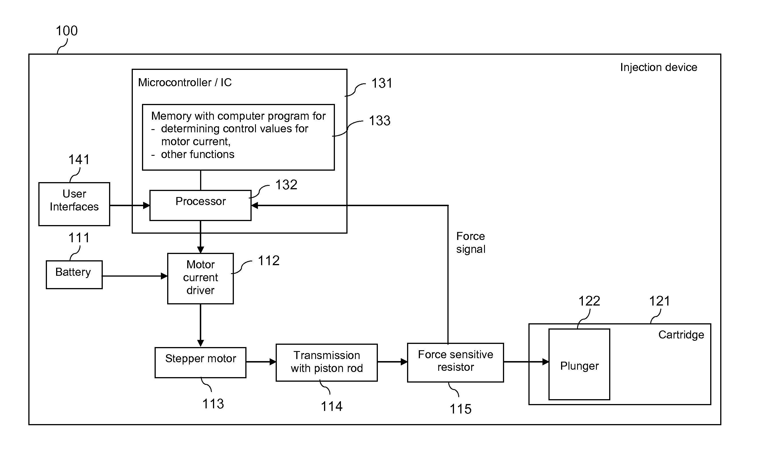
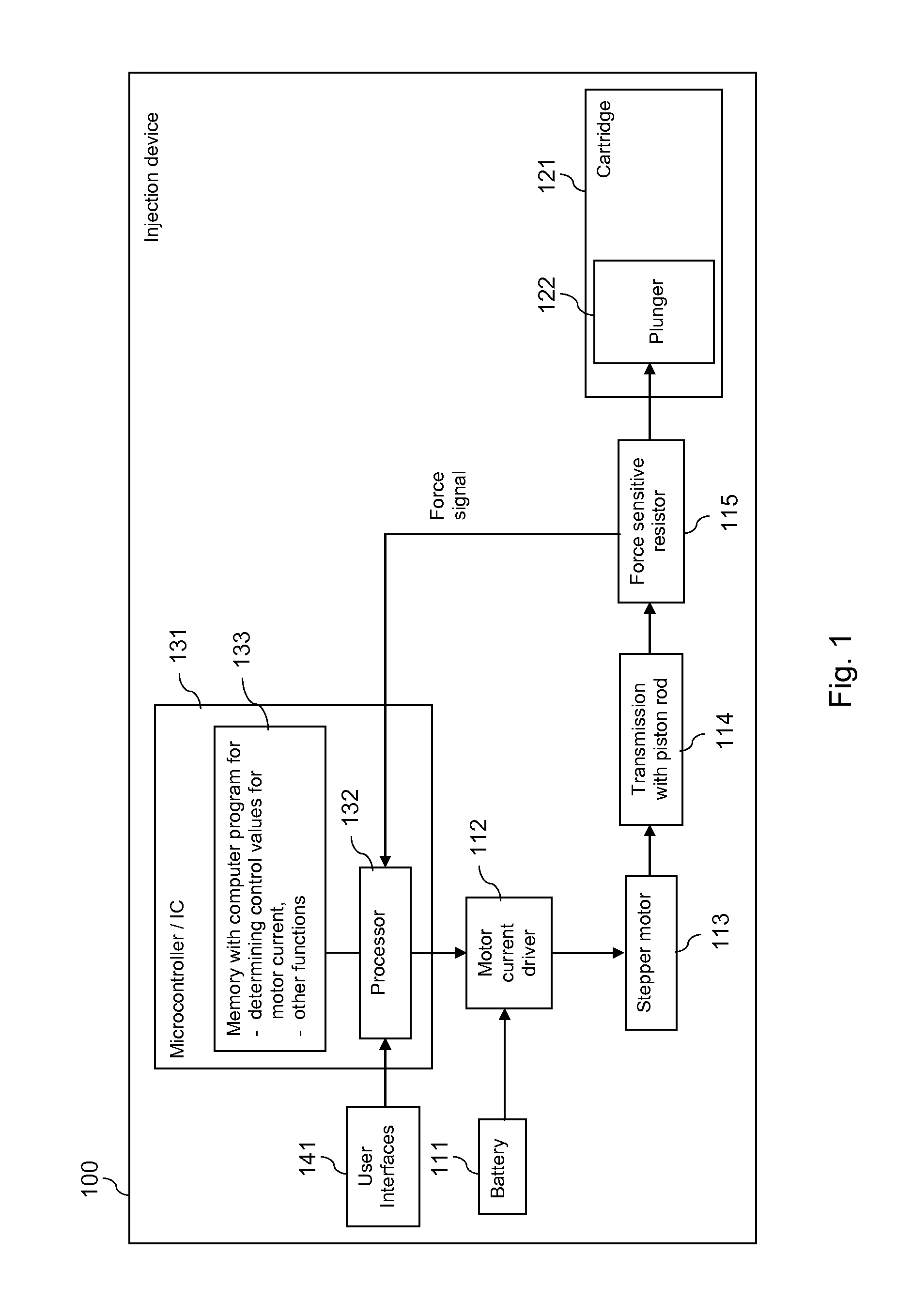
[0043]FIG. 1 is a schematic block diagram, which presents an injection device or apparatus 100 with a motor control according to an exemplary embodiment of the invention.

[0044]The injection device 100 could be for instance an injection pen, such as an insulin pen or an injection pen for another medicament.

[0045]The injection device 100 may comprise a battery 111. The battery can be exchangeable or non-exchangeable. It can further be rechargeable or non-rechargeable.

[0046]The battery 111 is arranged to supply power to a motor current driver 112 of the injection device 100. The motor current driver 112 is linked to a motor, for example to a stepper motor 113 of the injection device 100. The stepper motor 113 interacts with a transmission 114 of the injection device 100. The transmission 114 may comprise for example a piston rod that is moved by the stepper motor 113. The transmission 114 may further comprise a transmissions gear or gearbox, for example to reduce the speed and increase...


PUM


Abstract

In order to improve the energy efficiency of an injection device 100, a current is caused to be applied to a motor 113 of the injection device 100, which is related to a signal from a force sensor 115. The signal represents a force that is applied by the motor 113 to a plunger 122 of a cartridge 121.

Description

CROSS REFERENCE TO RELATED APPLICATIONS[0001]The present application is a 35 U.S.C. 371 National Application of PCT / EP2011 / 053832 filed Mar. 15, 2011, which claims priority to European Patent Application No. 10156668.5 filed Mar. 16, 2010, and, the entire contents of which are incorporated entirely herein by reference.FIELD OF THE INVENTION[0002]The invention relates to the field of injection devices, and more specifically to the control of a motor of an injection device for a medicament.BACKGROUND OF THE INVENTION[0003]An injection device, for example an injection pen, can be driven electromechanically by using a motor, which drives a transmission to force a liquid substance out of a container.[0004]The container may be a cartridge, for example for a medicament. The cartridge may have a cylindrical body made of glass, plastics, and / or the like. A first end of the cartridge may be closed by a septum which may be pierced by a needle. A second end of the cartridge may be closed by a p...

Claims


Application Information

Patent Timeline
Patent Type & Authority Patents(United States)
IPC IPC(8): A61M5/20A61M31/00A61M5/145A61M5/172A61M5/315
CPCA61M5/20A61M5/172A61M5/1452A61M2005/31588A61M2205/332A61M5/31546A61M5/31525A61M2205/8212
Inventor MULLER-PATHLE, STEPHANNESSEL, CHRISTIANEISSENGARTHEN, CHRISTOPHDURRANI, NAVID
Owner SANOFI AVENTIS DEUT GMBH
Why Eureka
Try Eureka