Electrical devices and methods of charging

a technology of electric devices and charging methods, applied in the direction of inductance, relays, transportation and packaging, etc., can solve the problems of difficult to find a suitable location for the secondary coil, the use of the charging platform with electrical devices, etc., and achieve the effect of reducing current induced

Inactive Publication Date: 2014-09-16
CITY UNIVERSITY OF HONG KONG
View PDF9 Cites 0 Cited by
  • Summary
  • Abstract
  • Description
  • Claims
  • Application Information

AI Technical Summary

Benefits of technology

[0010]According to the present invention there is provided an electrical device. The device includes a body having a portion formed with a circumference extending about an axis, a rechargeable battery housed within the body, a first connection circuit in connection with the rechargeable battery disposed within the body, and a removable cap adapted to fit over and at least partly surround the body portion. The cap includes an integrally formed secondary winding surrounding the body portion about the axis, the secondary winding being adapted to receive magnetic flux extending from a planar charging surface. The cap further includes a layer of magnetic material disposed between the secondary winding and the body portion for reducing current induced in the body of the electrical device, and a second connection circuit for connecting the secondary winding to the first connection circuit so as to charge the rechargeable battery in the body. The cap is arranged to be in contact with the planar charging surface and to support the electrical device on the planar charging surface during charging of the electrical device, and the secondary winding is arranged to be substantially parallel to the planar charging surface so that lines of magnetic flux extending from the planar charging surface pass substantially perpendicularly through the secondary winding during charging of the electrical device.
[0013]Preferably, especially if the body of the electrical device is formed of metal either completely or substantially, magnetic shielding may be provided between the secondary winding and the remainder of the body of the device so as to minimize the amount of flux that passes through the metal body and to minimize consequential induction heating in the body.
[0014]In another aspect, a cap for an electrical device is provided. The cap is removably fitted over and at least partly surrounding a body portion of an electrical device, and includes an integrally formed secondary winding surrounding the body portion, the secondary winding being adapted to receive magnetic flux extending from a planar charging surface, a layer of magnetic material disposed between the secondary winding and the body portion of the electrical device for reducing current induced in the body of the electrical device, and a connection circuit for connecting the secondary winding to the electrical device so as to charge a rechargeable battery in the electrical device. The cap is arranged to be in contact with the planar charging surface and to support the electrical device on the planar charging surface during charging of the electrical device, and the secondary winding is arranged to be substantially parallel to the planar charging surface so that lines of magnetic flux extending from the planar charging surface pass substantially perpendicularly through the secondary winding during charging of the electrical device.
[0015]In another aspect, an apparatus is provided. The apparatus includes a cap for an electrical device, the cap being adapted to be removably fitted over and at least partly surround a body portion of an electrical device. Further, the cap includes an integrally formed secondary winding to surround the body portion when present, the secondary winding being adapted to receive magnetic flux extending from a planar charging surface when present, and a layer of magnetic material situated such that when the cap is removably fitted over the body portion, the layer of magnetic material is disposed between the secondary winding and the body portion of the electrical device for reducing current induced in the body of the electrical device. The cap is configured for placing in contact with the planar charging surface when present and to support the electrical device on the planar charging surface during charging of the electrical device, and the secondary winding is arranged to be substantially parallel to the planar charging surface when present so that lines of magnetic flux extending from the planar charging surface pass substantially perpendicularly through the secondary winding during charging of the electrical device.

Problems solved by technology

A disadvantage with such conventional arrangements, however, is that with the proliferation in various types of portable electrical devices most users of such devices have to have a corresponding number of charging adaptors which may be mutually incompatible.
In practice, however, there may still be some issues that need addressing for the charging platform of WO03 / 105308 to gain widespread acceptance.
One issue, for example, is use of the charging platform with electrical devices that are not provided with an integral secondary coil.
However, for electrical devices of other shapes (especially devices with curved surfaces) finding a suitable location for the secondary coil may be less straightforward.

Method used


Image

  • Electrical devices and methods of charging
  • Electrical devices and methods of charging
  • Electrical devices and methods of charging

Examples


Embodiment Construction

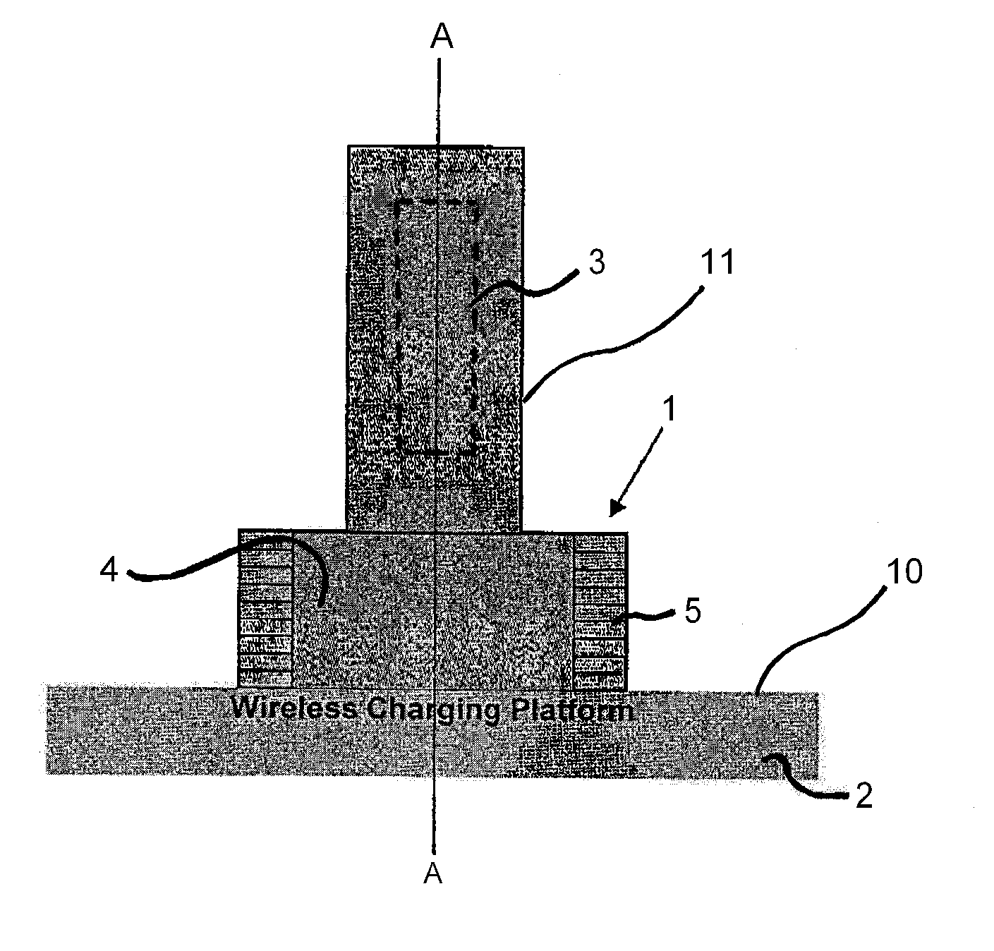
[0020]Referring to FIG. 1 there is shown an electric device such as a flashlight 1 that is placed on a planar charging surface 10 of a charging platform 2. The charging platform 2 is of the type described in WO03 / 105308, and in particular generates lines of magnetic flux that extend perpendicular to the charging surface. The flashlight 1 is provided with one or more rechargeable batteries (e.g., rechargeable battery 3) that are designed to be charged by the charging platform. The flashlight has a generally cylindrical main body portion 11 that houses the battery, and a head portion 4 that houses the light bulb, reflector and protective glass or plastic (not shown) in a conventional manner. The head portion 4 has a circular cross-section perpendicular to an axis A-A that extends through the head portion 4 and also through the main body portion 3 of the flashlight. It will be seen from FIG. 1 that when the flashlight 1 is to be charged, it is preferably placed on the charging surface ...


PUM

PropertyMeasurementUnit
circumferenceaaaaaaaaaa
magnetic fluxaaaaaaaaaa
currentaaaaaaaaaa

Abstract

An electrical device of the type having a rechargeable battery and which has a body having at least a portion formed with a circumference extending about an axis, is provided with a secondary winding adapted to receive magnetic flux from a planar charging surface that is arranged around the circumference in a plane perpendicular to the axis. Such a device may be charged by placing the device on a planar charging surface such that the body portion contacts the planar charging surface with the axis perpendicular to the charging surface and the secondary winding parallel to the charging surface.

Description

CROSS-REFERENCE TO RELATED APPLICATIONS[0001]This application claims priority to United Kingdom Application No. 0524790.3, filed Dec. 5, 2005, which is herein incorporated by reference in its entirety.FIELD OF THE INVENTION[0002]This invention relates to electrical devices, and in particular to electrical devices designed to facilitate their charging by means of a planar inductive charging platform.BACKGROUND TO THE INVENTION[0003]Conventionally, electrical devices that are operated by means of an internal rechargeable battery are provided with means for enabling that battery to be recharged as necessary. In the past such devices have been provided with a charging socket and a charging adaptor. The charging adaptor is usually an AC / DC adaptor that is connected to the electrical mains supply and normally outputs to the charging socket a controlled DC supply voltage suitable for charging a particular battery.[0004]A disadvantage with such conventional arrangements, however, is that wi...

Claims


Application Information

Patent Timeline
Patent Type & Authority Patents(United States)
IPC IPC(8): H02J7/00H01F38/14H02J7/02
CPCH02J7/025H01F38/14H02J50/10
Inventor WONG, HON, YEE
Owner CITY UNIVERSITY OF HONG KONG
Why Eureka
Try Eureka