Concrete exclusion structure

a technology of exclusion structure and concrete, which is applied in the direction of electrical apparatus casings/cabinets/drawers, couplings, gaseous cathodes, etc., can solve the problems of time-consuming and ineffective wrapping of coupler assemblies

Active Publication Date: 2014-09-23
BRIDGEPORT FITTINGS LLC
View PDF48 Cites 18 Cited by
  • Summary
  • Abstract
  • Description
  • Claims
  • Application Information

AI Technical Summary

Benefits of technology

[0012]A still further embodiment of the present invention is a concrete exclusion structure as described above, wherein at least one of the portions forming each end wall has at least one extending member dimensioned for overlying a portion of the other portion of the end wall so as to provide structural rigidity to the concrete exclusion structure when in the second, closed, configuration.
[0014]A still further embodiment of the present invention is a concrete exclusion structure as described above, further comprising a plurality of the score lines so as to allow positionment of the concrete exclusion structure between a first construction member and a second construction member which the concrete exclusion structure spans so that at least one of the score lines is positionable between the first and second construction members and thereby provides a weakened area allowing for fracture of the concrete exclusion structure along the score line positioned between the first and second construction member after the unhardened concrete has hardened relative to each construction member.

Problems solved by technology

Such wrapping of coupler assemblies has been found to be time consuming and not always efficacious in preventing uncured concrete from contacting such portions of the coupler assembly.

Method used


Image

  • Concrete exclusion structure
  • Concrete exclusion structure
  • Concrete exclusion structure

Examples


Embodiment Construction

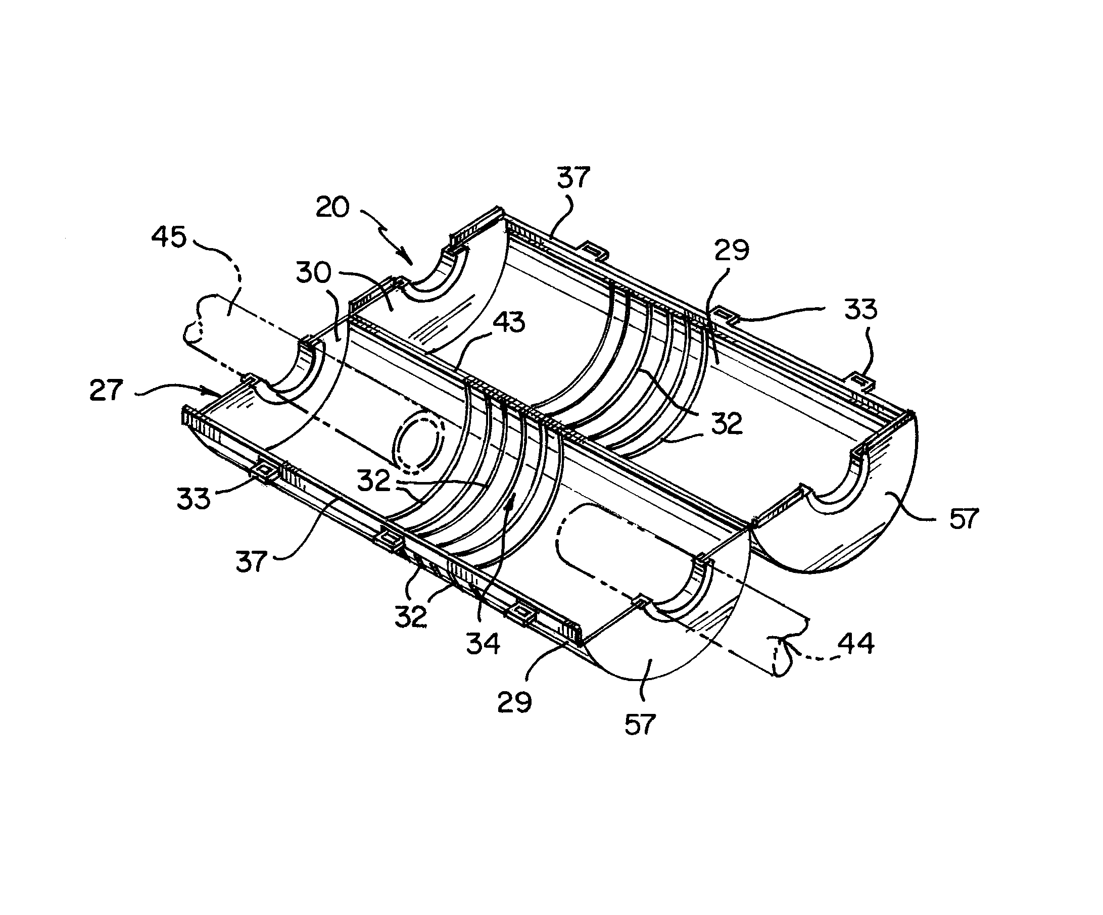
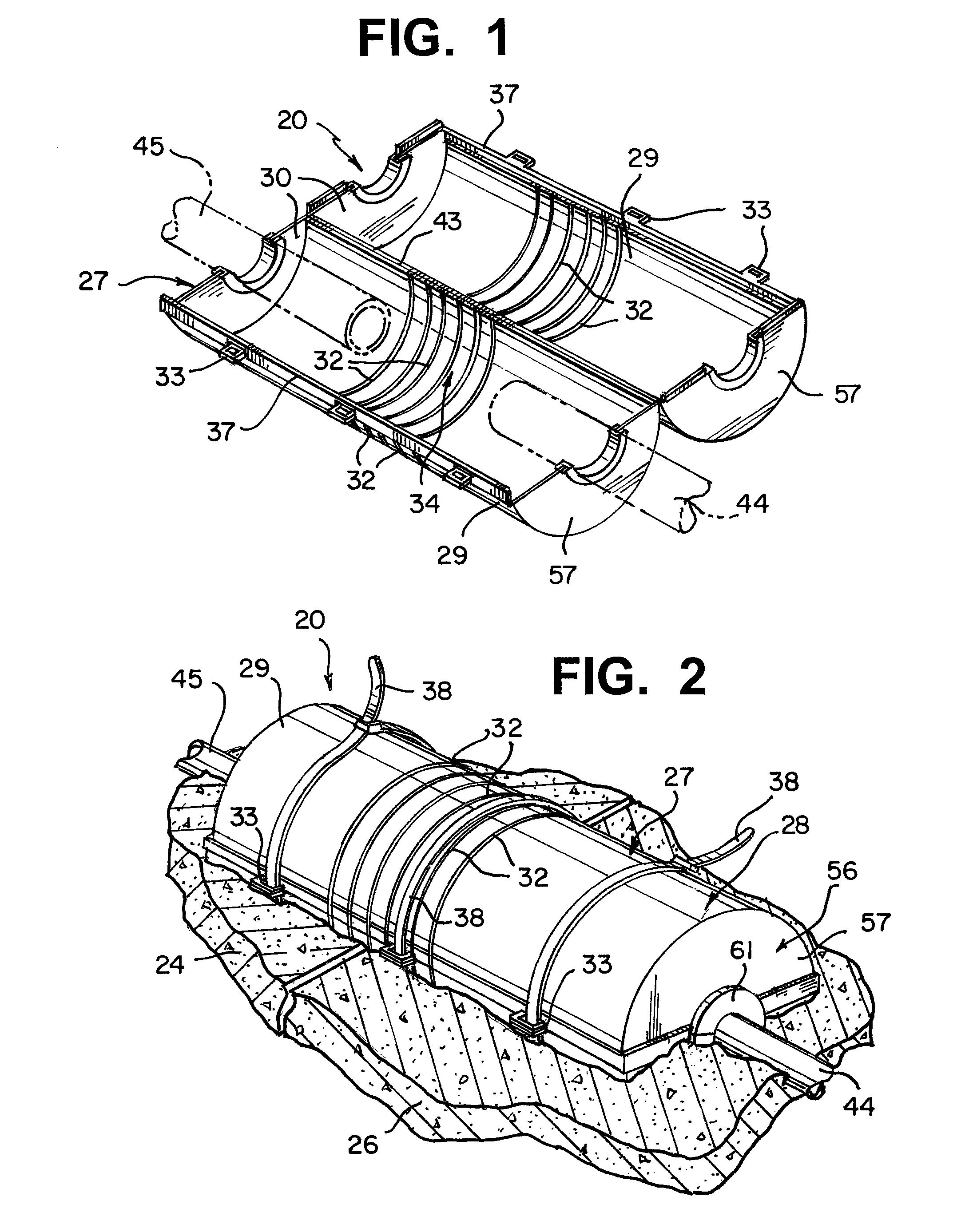
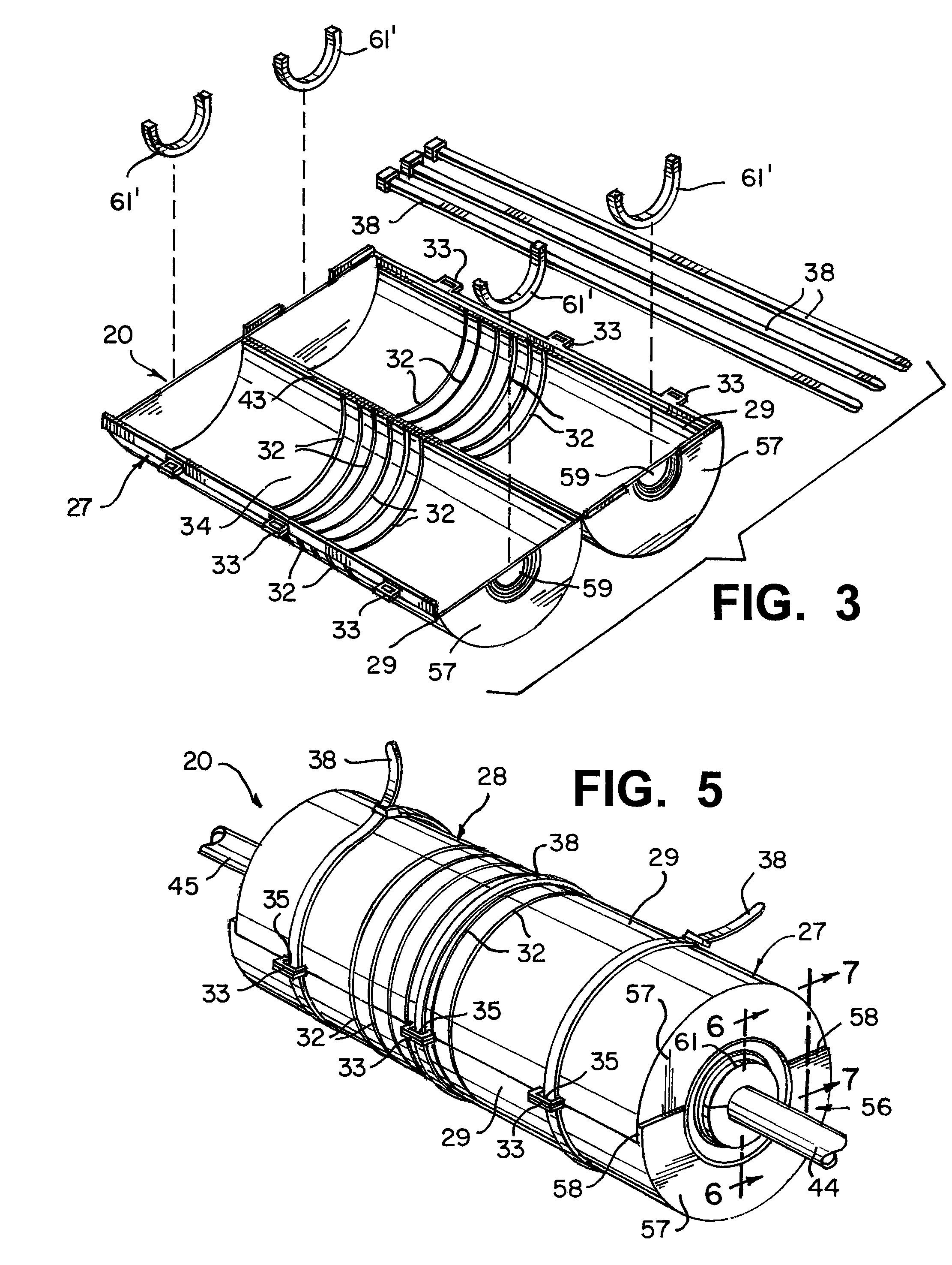
[0037]In many construction environments, it is necessary to provide electrical wiring between two construction members that may exhibit relative movement to each other. Such construction members are found, for example, in bridge sections, portions of parking garage floors, floor sections, building sections, and the like. In many situations, it is necessary to provide electrical wiring which will span such construction members and thereby there is a need to allow such wiring to be safely positioned in both construction members while allow movement of the construction members relative to each other.

[0038]The industry has thereby provided for various types of coupler assemblies which can house electrical wiring and still provide for relative movement of the construction members in which the coupler assembly is installed. In most situations, the coupler assembly, such as a telescoping coupler assembly 40 shown in FIG. 4, includes a coupler body 42 comprising an elongated cylinder of a p...


PUM


Abstract

A concrete exclusion structure is formed by a housing having a shell, end walls, and one or more score lines of reduced wall thickness. The housing defines an interior void that is dimensioned to enclose a coupler assembly. Knockouts in the end walls or knockout cones allow passage of tubes associated with the coupler assembly. The exclusion structure prevents uncured concrete from contacting the coupler assembly. The structure can fracture after the concrete has cured thereby allowing portions of the coupler assembly to move relative to each other. Such fracture is typically about one of the score lines.

Description

FIELD OF THE INVENTION[0001]The present invention is directed to a concrete exclusion structure for providing an internal void for placement of an electrical coupling assembly within the structure and thereby preventing uncured concrete from entering the void and coming into contact with the coupling assembly. Such exclusion structures are typically to be used where construction members formed from concrete are used in building, road, bridge and other types of construction.BACKGROUND OF THE INVENTION[0002]It is common in the construction industry to use concrete as a primary component of construction members, such as those used for bridge construction, auto garage construction, and other types of commercial and industrial construction. In many such situations, it is necessary for electrical wiring to be passed from one construction member to another, such as between one bridge section and an adjacent bridge section.[0003]It is common for a telescoping coupler assembly, such as that ...

Claims


Application Information

Patent Timeline
Patent Type & Authority Patents(United States)
IPC IPC(8): E04C3/00H02G3/08
CPCH02G3/088H02G3/083Y10T403/17
Inventor SMITH, LAWRENCE, J.
Owner BRIDGEPORT FITTINGS LLC
Why Eureka
Try Eureka