Cooling air intake structure for V-belt drive continuously variable transmission

a technology of continuously variable transmission and cooling air intake, which is applied in the direction of guards, couplings, cycle equipments, etc., can solve the problems of not being effective in preventing muddy water, and achieve the effects of preventing the flow of foreign matter through and reducing the risk of muddy water entering the cooling air inl

Inactive Publication Date: 2014-09-23
HONDA MOTOR CO LTD
View PDF28 Cites 23 Cited by
  • Summary
  • Abstract
  • Description
  • Claims
  • Application Information

AI Technical Summary

Benefits of technology

[0015]According to the present invention, the cooling air inlet can be spaced a long distance apart from muddy water and dust flung up by the rear wheel. The cooling air duct can be formed in a small size. Therefore, entry of muddy water and dust into the cooling air inlet can be suppressed. Further, the cooling air intake structure has the advantage of preventing muddy water flowing along the upper surface of the transmission case from flowing into the transmission case.
[0016]Muddy water and dust can be separated from cooling air by the U-shaped cooling air passage. Therefore, if the cooling air intake structure is provided with a filter, the life of the filter can be extended.
[0017]Flow of foreign matters through the cooling air inlet can be easily prevented by the body cover.
[0018]The cooling air passage is formed in a space covered with a laterally protruding side skirt of the body cover below the pillion footrest. Therefore, cooling air can flow smoothly through the space inside the side skirt to the cooling air inlet.
[0019]Intake air can flow smoothly through the cooling air passage to the inlet of the air cleaner. Consequently, the performance of the internal combustion engine can be improved.
[0020]The cooling air duct is attached to the flat part beside the drive pulley. Therefore, intake noise generated by intake air flowing through the cooling fan side opening formed in the transmission case can be absorbed and noise suppressing effect can be improved.

Problems solved by technology

This cooling air intake structure is effective in preventing muddy water and dust coming from the front from entering the cooling air intake structure, but is not necessarily effective in preventing muddy water and dust raised up by the rear wheel from entering the cooling air intake structure.

Method used


Image

  • Cooling air intake structure for V-belt drive continuously variable transmission
  • Cooling air intake structure for V-belt drive continuously variable transmission
  • Cooling air intake structure for V-belt drive continuously variable transmission

Examples


Embodiment Construction

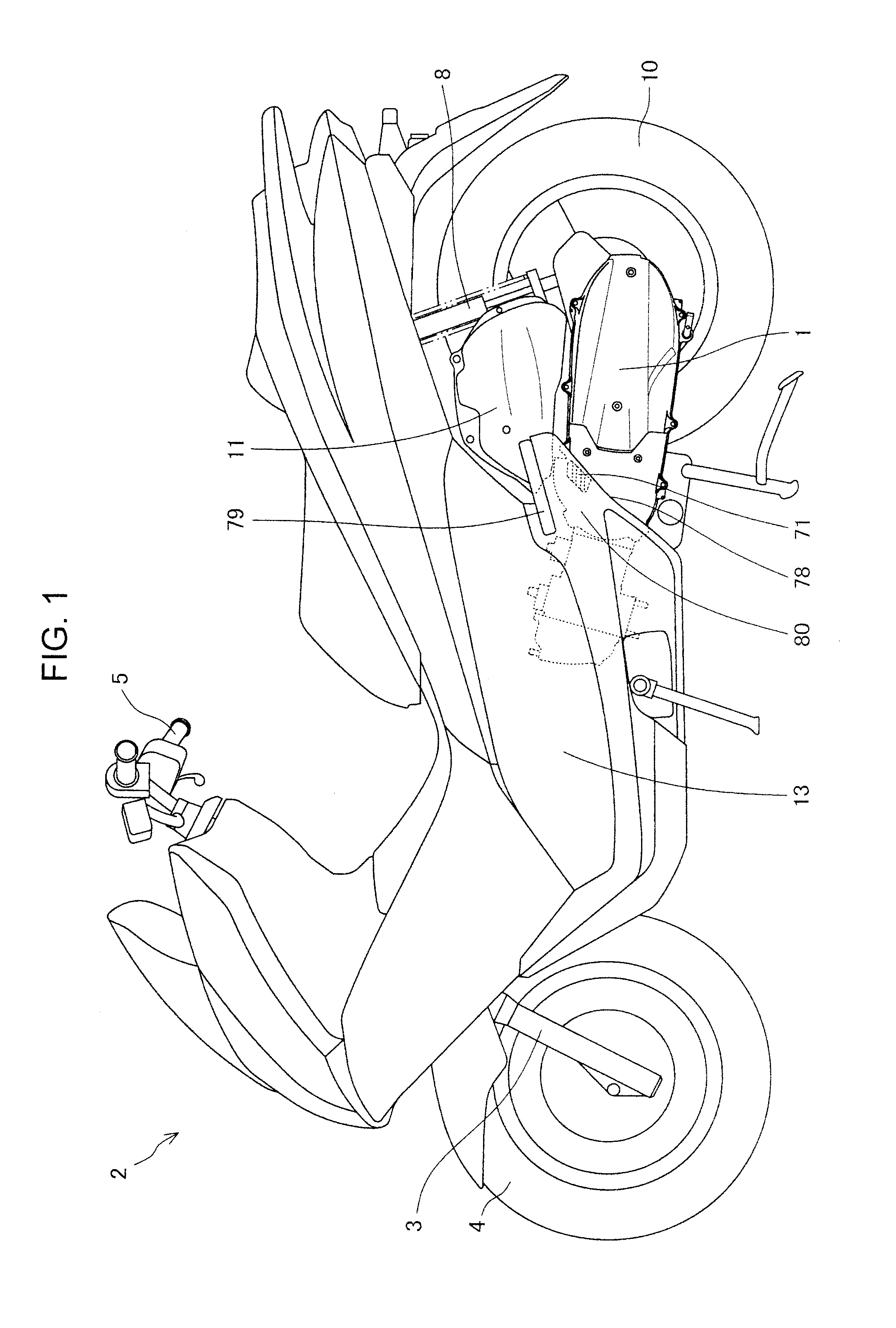
[0040]FIG. 1 is a side elevation of a motorcycle 2 provided with a power unit 1 relating to a preferred embodiment of the present invention. The motorcycle 2 has a body frame formed by assembling a head pipe, a main frame extending obliquely downward toward the rear from the head pipe, right and left rear frames connected to the rear end of the main frame and extending obliquely upward toward the rear, and some frames. A front wheel 4 is rotatably supported on the lower end of a front fork 3 which is rotatably supported on the head pipe. A handlebar 5 is connected to an upper end part of the front fork 3.

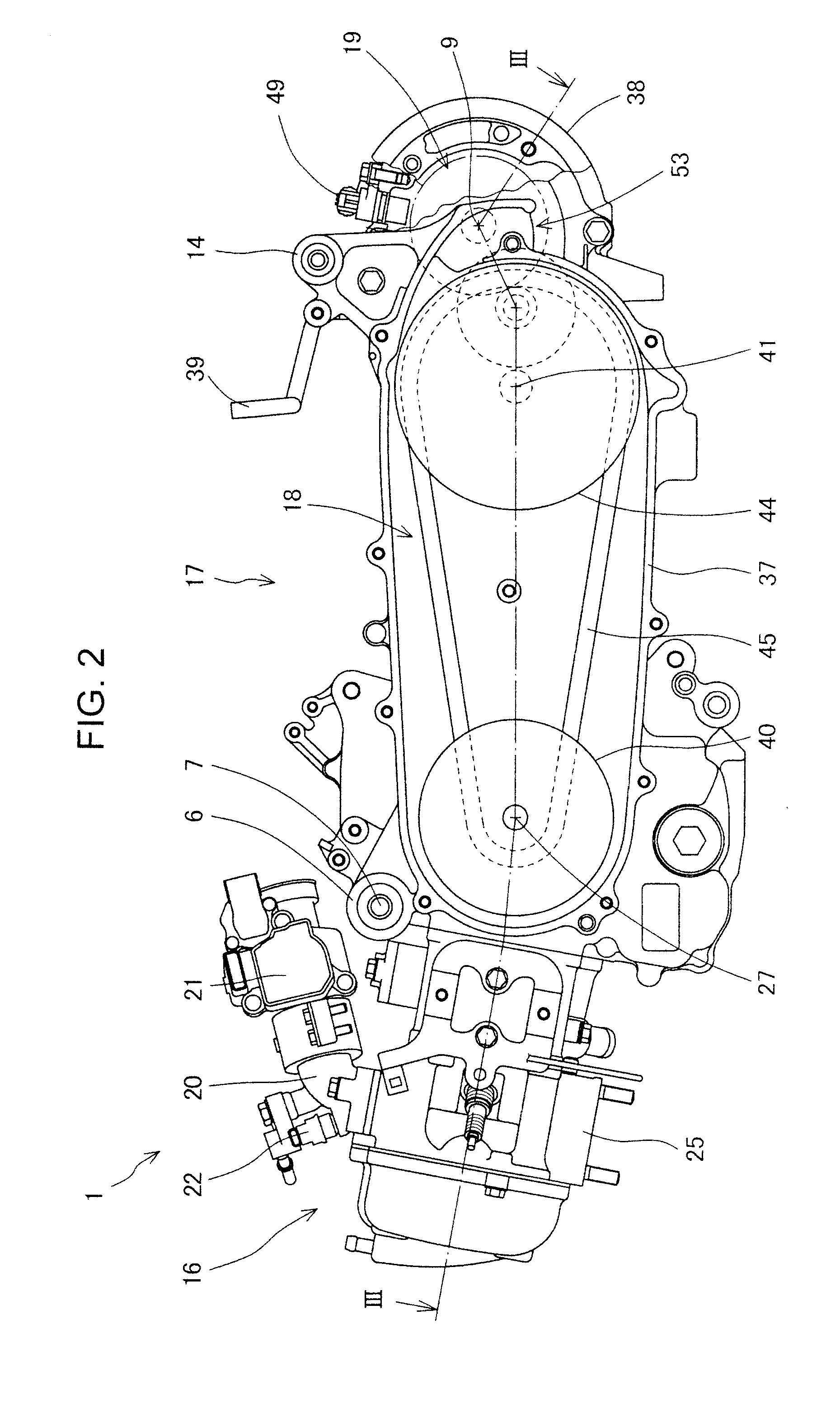
[0041]The power unit 1 is suspended from the rear frame by connecting a hanger 6 (FIG. 2) formed integrally with a front part of the power unit 1 to a bracket fixed to the rear frame by a support shaft 7. A rear cushion 8 is extended between a bracket 14 (FIG. 2) formed on a rear end part of the power unit 1, and a bracket formed on a rear end part of the rear frame. Thus, the power...


PUM


Abstract

Disclosed is a cooling air intake structure for a V-belt drive continuously variable transmission, which is disposed beside the rear wheel of a small vehicle and which does not permit muddy water and dust to enter therein. A cooling air inlet through which cooling air is taken in is formed at a position beside a transmission case and above a cooling fan side opening formed in the transmission case opposite to a drive pulley. A cooling air passage extending from the cooling air inlet to the side opening is formed so as to surround the side opening. Cooling air taken in through the cooling air inlet is guided so as to flow upward first and then flows downward along a U-shaped cooling air passage to the side opening of the transmission case beside the cooling fan.

Description

TECHNICAL FIELD[0001]In V-belt drive continuously variable transmissions for vehicles, frictional heat is generated by frictional contact between a V-belt and a drive pulley and between the V-belt and a driven pulley. The present invention relates to a cooling air intake structure for taking cooling air into the V-belt drive continuously variable transmission when those component parts need cooling.BACKGROUND ART[0002]A known air intake structure described in Patent Literature 1 has an air inlet opening toward the rear of the vehicle. This cooling air intake structure is effective in preventing muddy water and dust coming from the front from entering the cooling air intake structure, but is not necessarily effective in preventing muddy water and dust raised up by the rear wheel from entering the cooling air intake structure.[0003]Patent Literature 1: JP Utility Model Publication S63-17695 (FIG. 5)SUMMARY OF THE INVENTIONTechnical Problem[0004]It is an object of the present invention...

Claims


Application Information

Patent Timeline
Patent Type & Authority Patents(United States)
IPC IPC(8): F16D1/00F16H57/04B60K11/00B60K11/08B60K17/08F16H57/02F16H57/035
CPCF16H57/0489B60K11/08F16H57/035B60K17/08F16H2057/0203F16H57/0416B60Y2200/126B60Y2200/12F16H2057/02065B62J50/30F16H57/02B62M7/00B60K17/06
Inventor YAMANISHI, TERUHIDEKOMURO, HIROKAZUTSUCHIYA, RYUJIHORII, NOBUTAKAKASHIMA, HIDEO
Owner HONDA MOTOR CO LTD
Why Eureka
Try Eureka