
Accelerator pedal depression force control device

a technology of depression force and accelerator pedal, which is applied in the direction of electrical control, mechanical control devices, instruments, etc., can solve the problems of increasing the depression force, the acceleration pedal may be excessively depressed by the reaction, and the acceleration pedal is not easy to feel the sudden increase of the depression force, so as to reduce the amount of the acceleration pedal's depression force

Active Publication Date: 2014-09-30
NISSAN MOTOR CO LTD
View PDF30 Cites 8 Cited by
  • Summary
  • Abstract
  • Description
  • Claims
  • Application Information

AI Technical Summary

Benefits of technology

The invention helps the driver to feel the increase in the accelerator when the opening degree is greater than a certain threshold. This happens while decreasing the amount of depression force on the accelerator.

Problems solved by technology

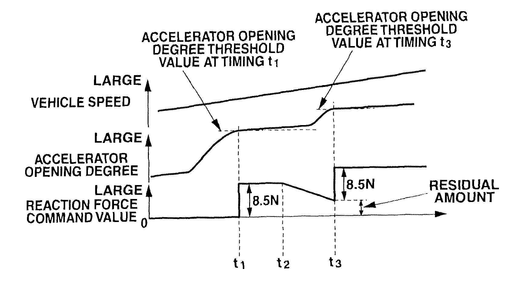
In this case, when the increase amount of the depression force is suddenly returned (decreased) in a case where the increase amount of the depression force immediately increased when the driving region enters from the second driving region to the boundary driving region is restored (returned), the accelerator pedal may be excessively depressed by that reaction.
However, in a case where this increase amount of the depression force is gradually returned, the increase amount of the depression force becomes small when the depression force needs to suddenly increase in the middle of the gradual return of the increase amount of the depression force.
Accordingly, there is generated a problem that the driver cannot feel the sudden increase of the depression force, that is, a wall feeling which is the depression feeling of the accelerator pedal.

Method used


Image

  • Accelerator pedal depression force control device
  • Accelerator pedal depression force control device
  • Accelerator pedal depression force control device

Examples


Embodiment Construction

[0016]Hereinafter, one embodiment of the present invention will be illustrated in detail with reference to the drawings.

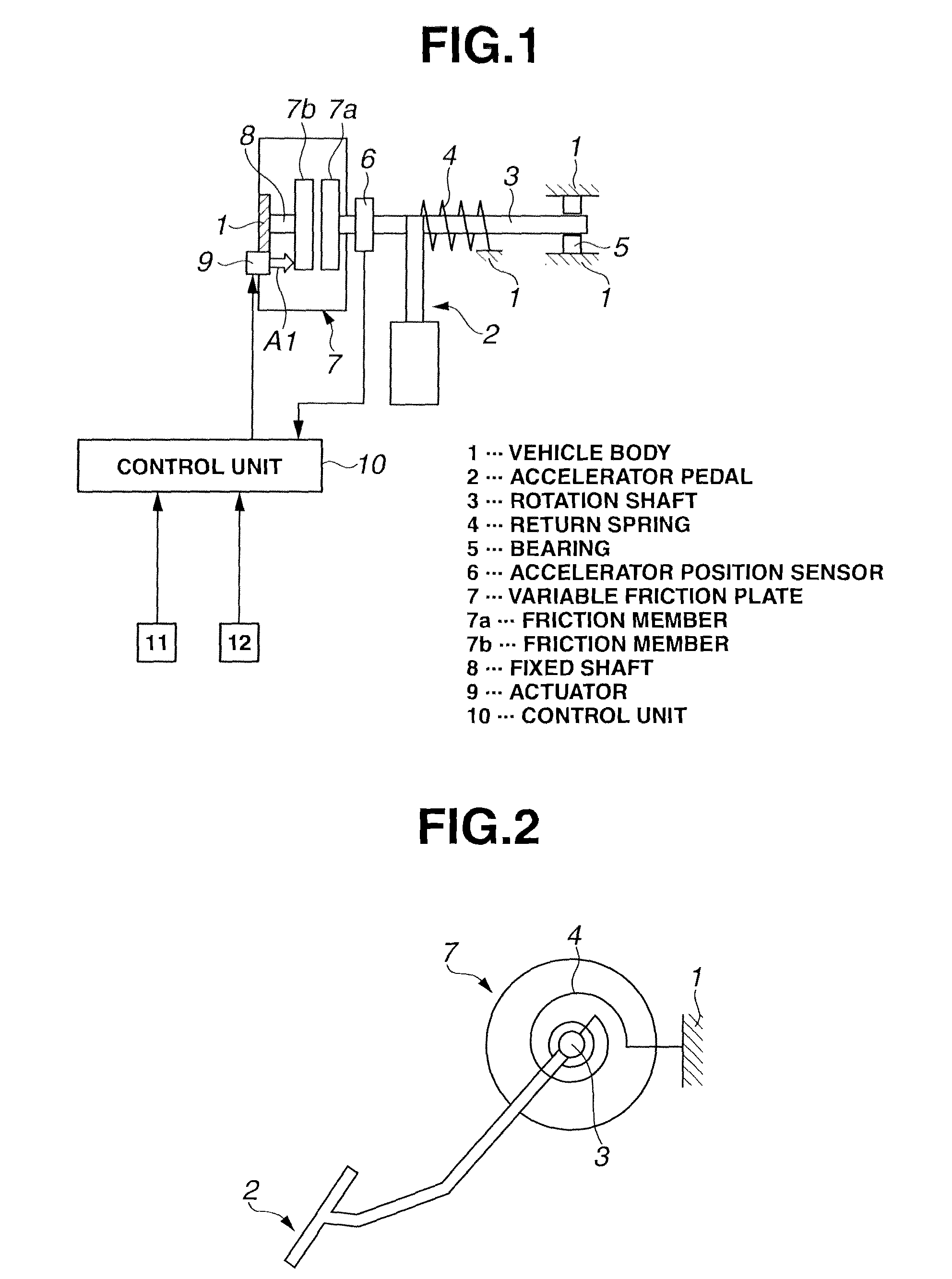
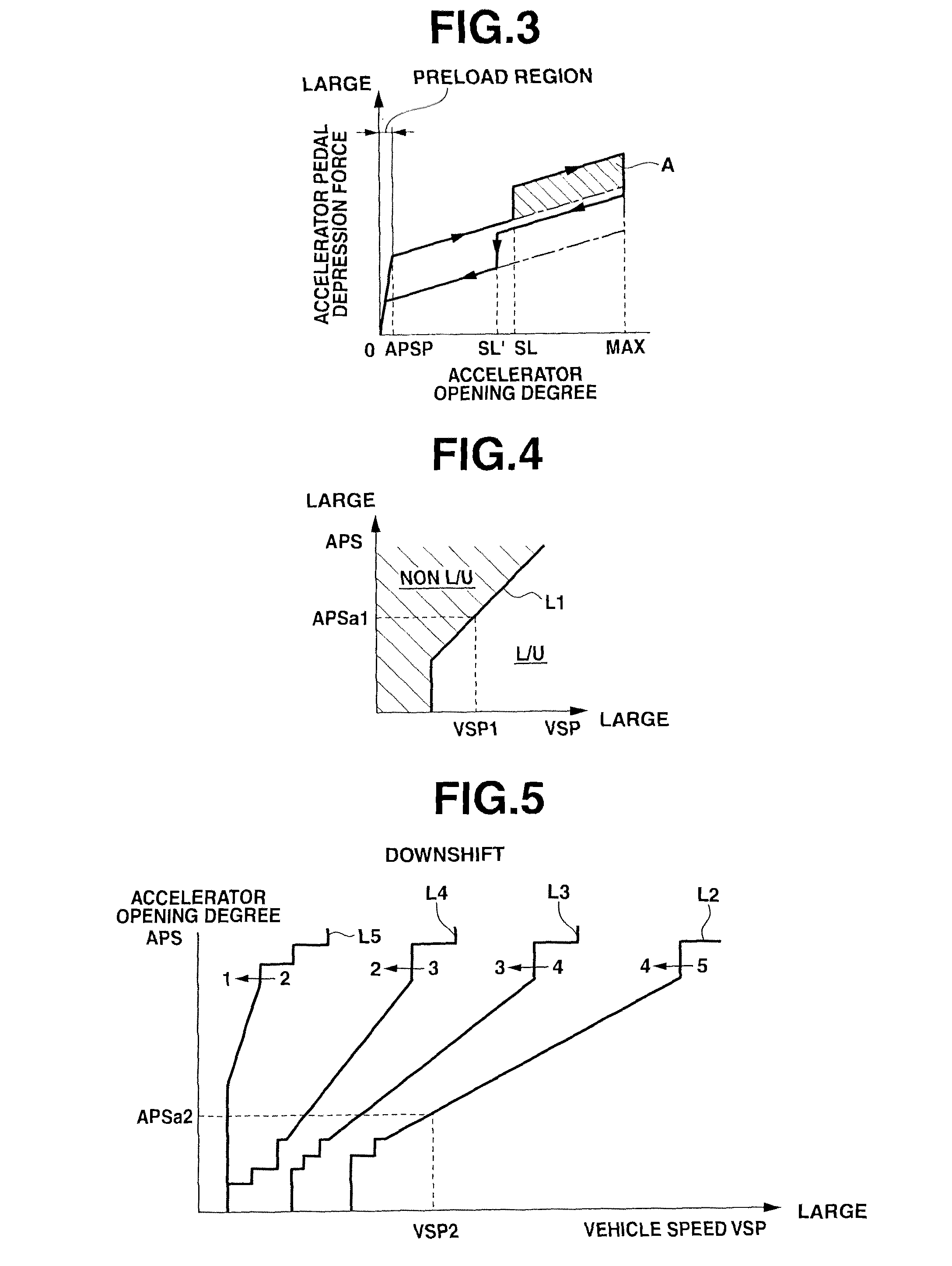
[0017]This accelerator pedal depression force control apparatus is basically configured to variably control a depression force (operation reaction force) of an accelerator pedal 2 provided to a vehicle body 1 of a vehicle (not shown). As described below, the accelerator pedal depression force control apparatus includes a means configured to sense an opening degree (depression amount) of the accelerator pedal 2 provided to the vehicle, and a means configured to vary the depression force of the accelerator pedal 2 from a base depression force. The accelerator pedal depression force control apparatus is configured to increase the depression force of the accelerator pedal 2 than (beyond) the base depression force in a region where the opening degree of the accelerator pedal 2 is greater than a predetermined accelerator pedal opening degree threshold value.

[0018]As show...


PUM


Abstract

When the accelerator opening degree becomes equal to or smaller than an increase amount cancel threshold value (timing t2) while the depression force of an accelerator pedal 2 is increased than a base depression force by a predetermined increase amount of the depression force, the predetermined increase amount of the depression force is decreased at a predetermined rate, and moreover, when the accelerator opening degree becomes greater than a predetermined accelerator opening degree threshold value (timing t3) while the predetermined increase amount of the depression force is decreased, the depression force of the accelerator pedal 2 is increased with respect to the base depression force so that the increase amount of the depression force with respect to the base depression force becomes greater than the predetermined increase amount of the depression force.

Description

TECHNICAL FIELD[0001]This invention relates to an accelerator pedal depression force control apparatus.BACKGROUND ART[0002]A Patent Document 1 discloses an art that is applied to an engine arranged to switch a first driving method (for example, homogeneous combustion) on a high rotation and high load side, and a second driving method (for example, stratified charge combustion) on a low rotation and low load side on which a fuel economy efficiency is higher than that of the first driving method, and that is configured to immediately increase a depression reaction force (depression force) of an accelerator pedal when the driving region of the engine enters a boundary driving region just before the switching to the first driving region when the driving region of the engine is switched from the second driving region in which the second driving method is performed, to the first driving region in which the first driving method is performed. This increase amount of the depression force is ...

Claims


Application Information

Patent Timeline
Patent Type & Authority Patents(United States)
IPC IPC(8): G05G1/30B60K26/02F02D11/02G05G1/38
CPCG05G1/38B60K26/02F02D11/02B60K2026/023Y10T74/20534B60K26/00F02D11/00F02D41/04
Inventor SAKAGUCHI, SHIGEYUKISHIOMI, MASAOOMORI, MASAHIRO
Owner NISSAN MOTOR CO LTD
Learn More