

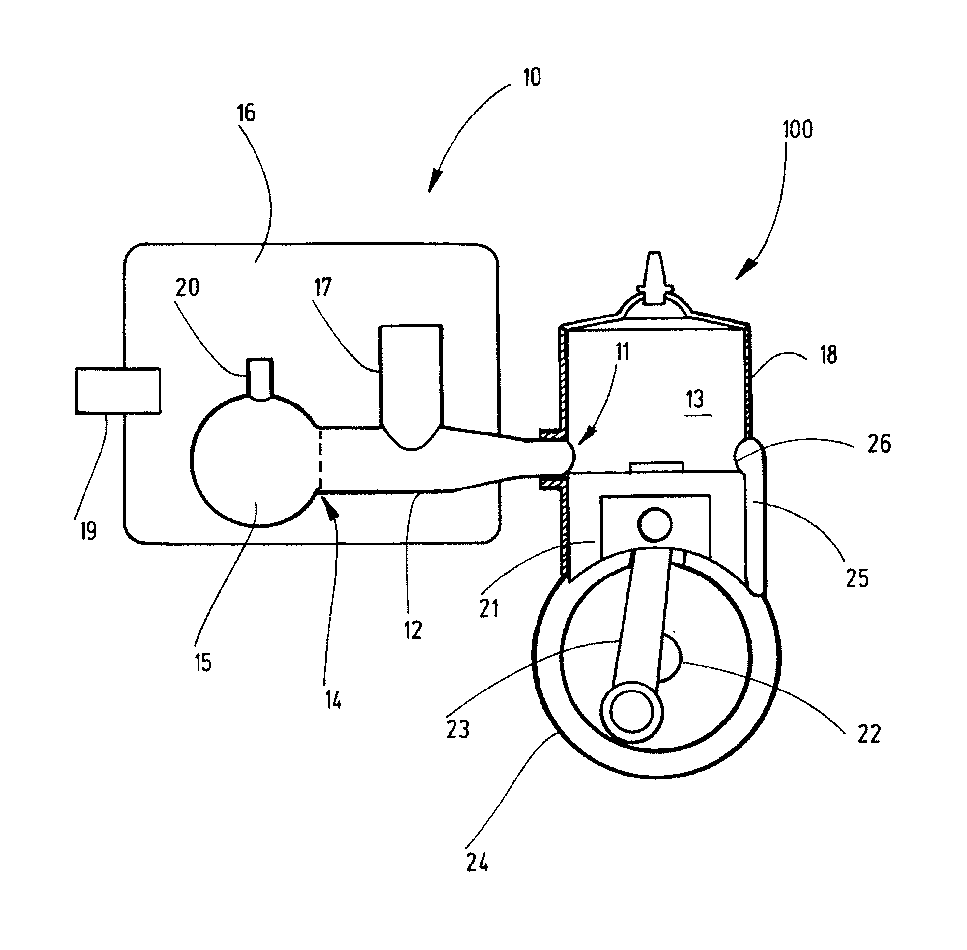
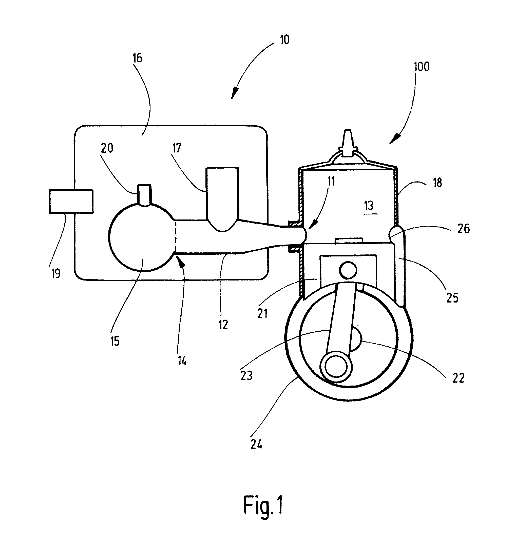
Two-stroke engine comprising a muffler
a two-stroke engine and muffler technology, which is applied in the direction of machines/engines, mechanical equipment, instruments, etc., can solve the problems of uncontrollable flow of uncombusted fuel-air mixture into the combustion space of the two-stroke engine, inability to completely prevent the escape of uncontrollable uncontrollable uncontrollable uncontrollable uncontrollable uncontrollable uncontrollable uncontrollable uncontrollable uncontrollable uncontroll
- Summary
- Abstract
- Description
- Claims
- Application Information
AI Technical Summary
Benefits of technology
Problems solved by technology
Method used
Image

Examples
Embodiment Construction
Object, Solution, Advantages
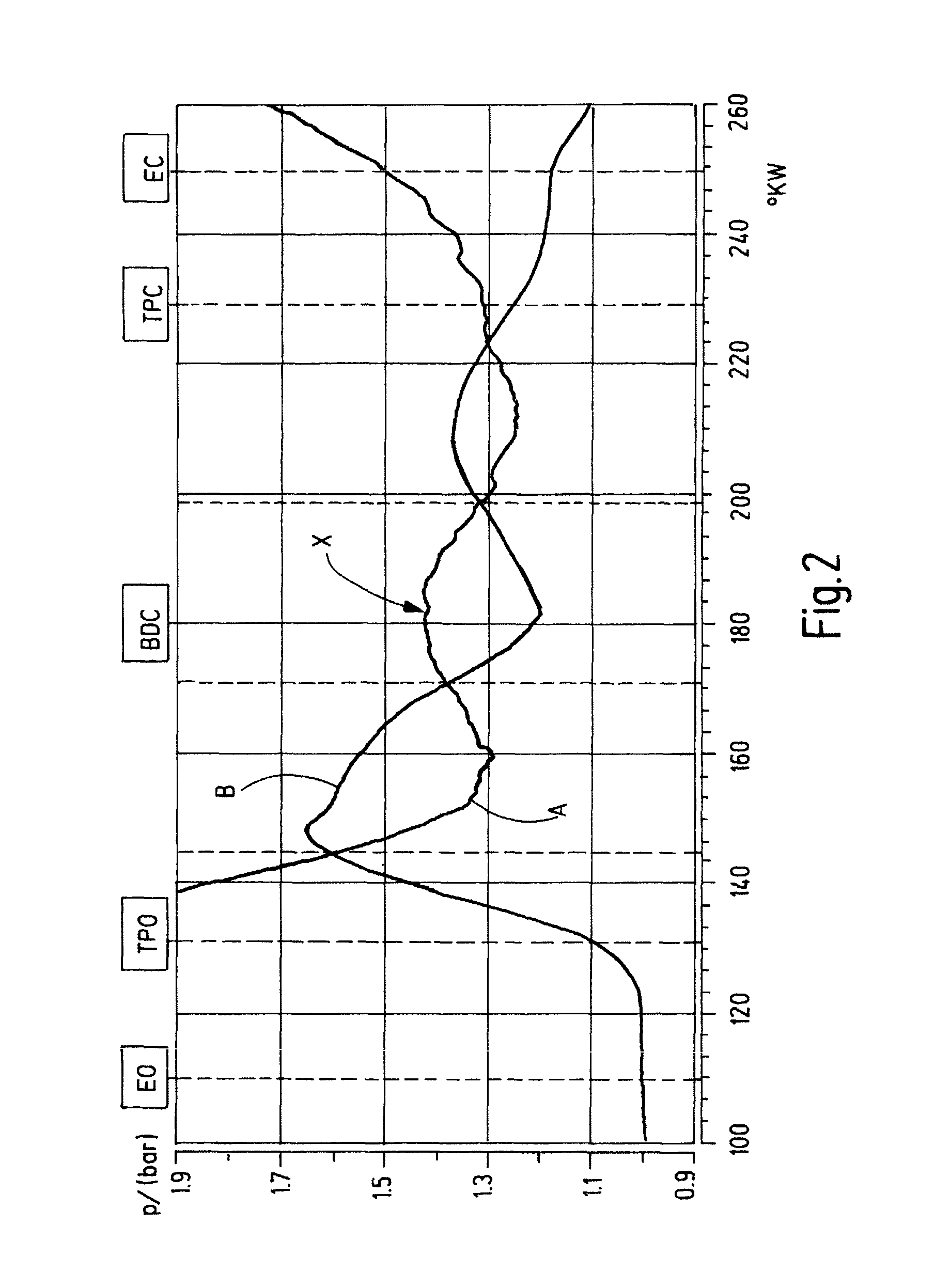
[0011]It is therefore the object of the present invention to further develop a two-stroke engine with a muffler of the type described above so that the flow behavior of the fuel-air mixture into the combustion space of the two-stroke engine is improved, it is the object of the present invention in particular to prevent that fuel-air mixture enters the muffler in the uncombusted state and in particular to control the quantity of fuel-air mixture which enters the combustion space via the overflow channel. The object of the present invention is to influence the pressure fluctuations of the exhaust gas on exiting the muffler through a corresponding adaptation of the volumes involved on the muffler. The object of the present invention, in particular, is to achieve a preferably major noise reduction of the operation of the two-stroke engine.
[0012]Starting out from a two-stroke engine with a muffler of the type described above, this object is solved according to...
PUM
 Abstract
Description
Claims
Application Information