Fuel tank having a built-in auxiliary tank

a fuel tank and auxiliary tank technology, applied in the field of fuel tanks, can solve the problems of difficult and expensive manufacture, limited application, complex design and only applicable, etc., and achieve the effects of simple and fast connection, low cost, and low cos

Active Publication Date: 2014-09-30
MAGNA STEYR FUEL SYST
View PDF27 Cites 6 Cited by
  • Summary
  • Abstract
  • Description
  • Claims
  • Application Information

AI Technical Summary

Benefits of technology

[0007]The object is achieved by providing an insert in the fuel tank. Due to the fact that the insert is a box which is open at the top, it is cheap to manufacture and can be simply and fast connected by integral bonding to the wall of the tank. The economy of space achieved thereby allows providing a relatively large space in the interior of the insert while its space requirement in the tank is small. The insert offers space for all kinds of inner parts and additionally has functional advantages when used as a debubbling tank.
[0008]The insert is a component comprising surfaces forming an open space; thus it can be injection-molded in a simple mold or pressed from a planar starting material. The course of the upper rim of the side walls can easily be adapted to the spatial shape of the wall of the fuel tank, wherein the wall is at the same time the lid which closes up the insert towards the top.
[0009]The open shape of the insert also allows providing intermediate walls as installation parts in the insert without additional expenditure during manufacturing, wherein the intermediate walls can likewise be sealingly connected to the wall. The liberty of shaping the insert also allows forming the bottom of the insert to be inclined so as to ensure discharging largely irrespective of its position.
[0010]In order to obtain a sealed and durable weld connection, the weld flange at the upper rim of the side walls of the insert includes a weld flange which extends wholly around and comprises a root rib immerging into the wall of the fuel tank and advantageously having a wedge-shaped cross section. The root rib extending towards its pointed rim easily enters into the warm plastic shell, assumes its temperature exceptionally fast and in this way forms a firm connection therewith. Therefore the insert does not have to be heated for its installation, rendering installation easier. The intermediate walls in the insert can also wholly or partly be provided with such a weld flange.

Problems solved by technology

This design is complex and only applicable in the case of a planar top wall made of sheet metal.
And even then its durability remains questionable because of the tolerances and because of residual stresses caused by the welding process.
For this purpose, the wall is provided with undercut support parts, rendering its manufacture difficult and expensive.
Also, the body fixed by screws is a likewise complicated part; on top of that, its assembly is very complex.

Method used


Image

  • Fuel tank having a built-in auxiliary tank
  • Fuel tank having a built-in auxiliary tank
  • Fuel tank having a built-in auxiliary tank

Examples


Embodiment Construction

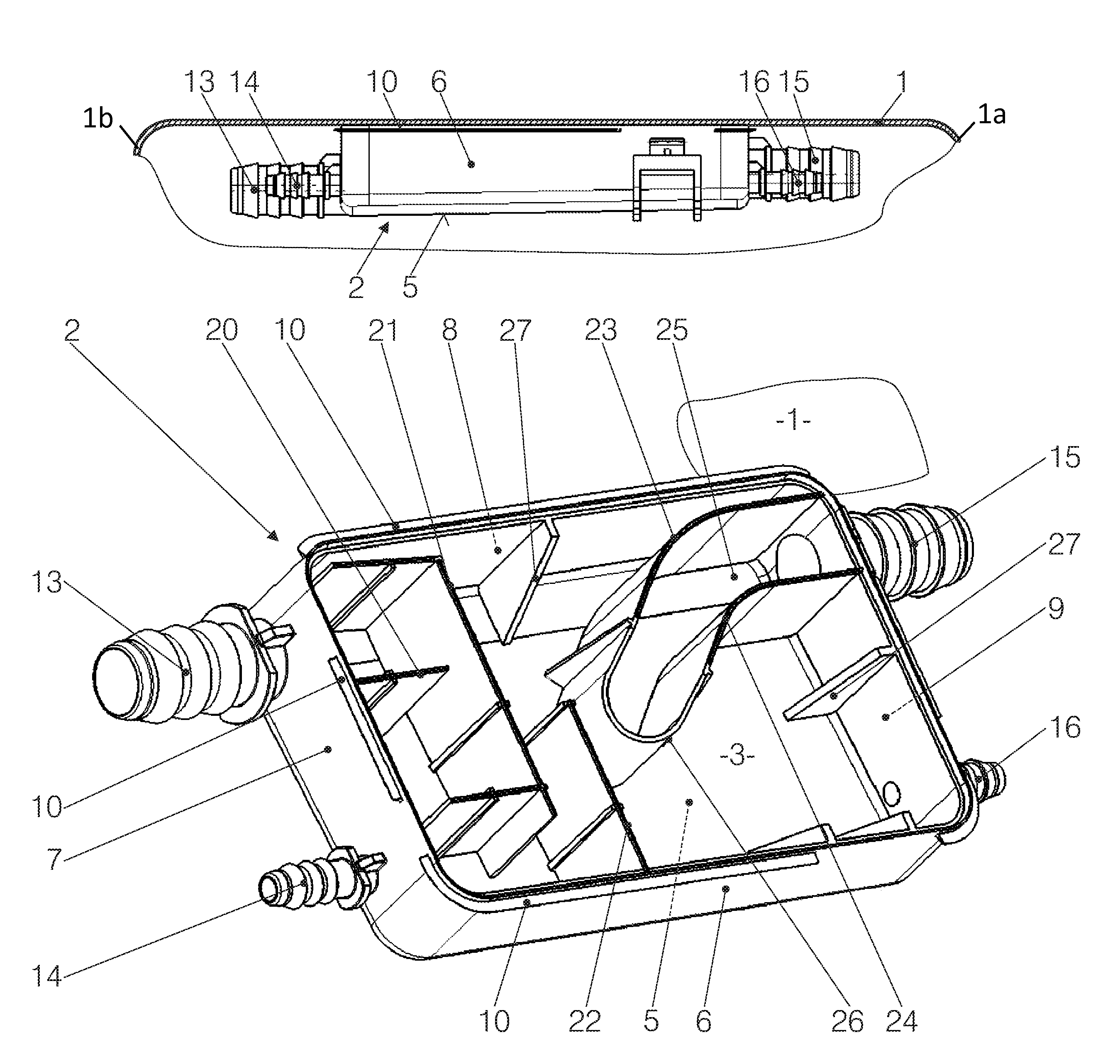
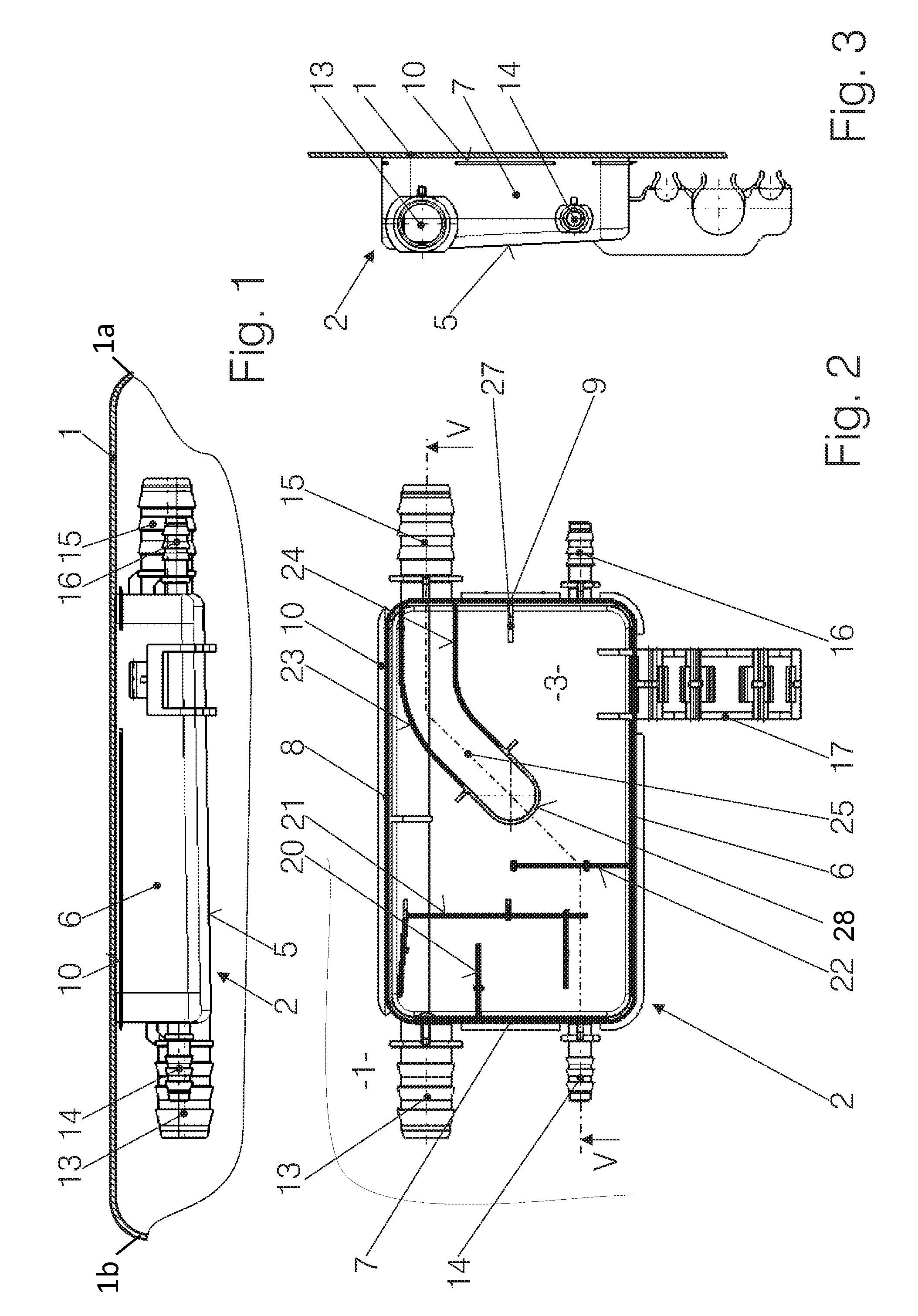
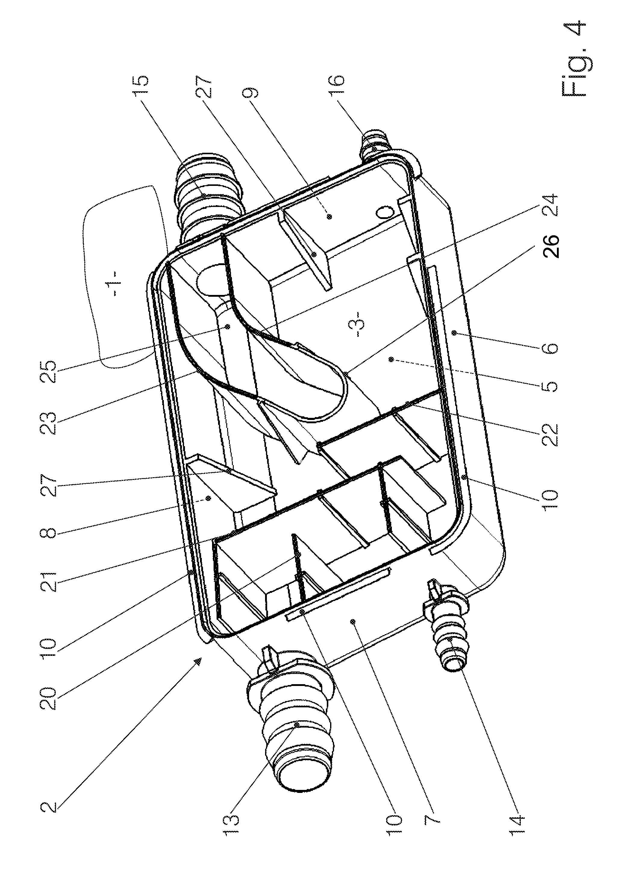
[0020]FIGS. 1 to 5 show a torn-off part only of the top wall 1 of a fuel tank and an insert 2 attached to the inside of the top wall 1 (and portions of walls 1a and 1b), wherein the insert 2 forms a closed space 3. The insert 2 is a component having the shape of a box which is open at the top and consisting of a slightly inclined (see FIG. 3) bottom 5 and vertical side walls 6, 7, 8, 9. The box may also have a cylindrical or otherwise shaped side wall. The upper rims of the side walls 6, 7, 8, 9 have a weld flange 10 integrally bonded to—welded to—the wall of the fuel tank.

[0021]A first connection piece 13 and a second connection piece 14 protrude from the side wall 7, a third connection piece 15 and a fourth connection piece 16 protrude from the side wall 9. The connection pieces 13, 14, 15, 16 are integral with the side walls 7, 9 and provide a connection between the space 3 in the interior of the insert 2 and pipes or hoses. Neither the pipes or hoses nor their target stations ar...


PUM


Abstract

A fuel tank made of plastic, in the interior of which an insert (2) is located, wherein the insert should enclose a space (3), wherein the fuel tank should offer the greatest possible economy of space, and the fuel tank and the insert should have a simple form. For this purpose, a box made of plastic and open at the top is attached to the inside of the upper wall (1) of the fuel tank as an insert (2), wherein the box forms a closed space (3) together with the wall (1) of the tank, wherein the insert (2) comprises a bottom (5) and side walls (6, 7, 8, 9), the upper edges of which are connected in a bonded manner to the wall (1) of the tank. The insert (2) contains inner parts (20-26) that are integral therewith and has at least one fitting (13-16) on the side walls (6, 7, 8, 9) for connecting a pipe line.

Description

BACKGROUND OF THE INVENTION[0001]The invention relates to a fuel tank made of plastic for motor vehicles, wherein an insert enclosing a space is located in the interior of the fuel tank. The wall of the fuel tank may consist of a single blow-molded piece having a sufficiently large opening or of two pressed or deep-drawn plastic shells which are subsequently joined together. The mentioned shaping processes use a mold, wherein the plastic is molded at a warm state. The walls may also be multilayered in order to minimize permeation of fuel vapors. The insert may be of different kinds; usually it is part of a venting system, such as a separator, a debubbling tank and / or a float chamber.[0002]In the case of conventional fuel tanks made of plastic, the parts of the venting system are individually mounted at the inside of the upper shell either by welding (see, for example, EP 1 310 715 A1) or by attaching them to weld crowns secured in through-holes of the shell (see, for example, EP 1 0...

Claims


Application Information

Patent Timeline
Patent Type & Authority Patents(United States)
IPC IPC(8): B65D88/12
CPCB60K15/03177Y10T137/86324B60K15/035
Inventor POZGAINER, GUENTHERPOLIFKE, MARK
Owner MAGNA STEYR FUEL SYST
Why Eureka
Try Eureka