Check patentability & draft patents in minutes with Patsnap Eureka AI!

Water jet propulsion watercraft

a watercraft and water lock technology, applied in the field of water jet propulsion watercraft, can solve the problems of difficult coordination of water lock and catalytic converter unit vibration, easy damage of the connecting portion between the water lock and the catalytic converter unit, and the increased likelihood of engine vibration, so as to prevent the damage to the exhaust system caused by engine vibration, the effect of reducing engine vibration

Active Publication Date: 2014-09-30
YAMAHA MOTOR CO LTD
View PDF6 Cites 1 Cited by
  • Summary
  • Abstract
  • Description
  • Claims
  • Application Information

AI Technical Summary

Benefits of technology

The solution effectively reduces engine vibrations transmitted to the catalytic converter, preventing damage and maintaining the alignment of the catalyst, thus ensuring the integrity of the exhaust system and improving the operational efficiency of the catalytic converter.

Problems solved by technology

As a result, the catalytic converter unit is more likely to experience such troubles as the position of the catalyst shifting out of place and the catalyst becoming damaged.
If the water lock is fixed to a hull of the watercraft, then it will be difficult for the water lock and the catalytic converter unit to vibrate in a coordinated manner even if vibrations from the engine cause the catalytic converter unit to vibrate.
Consequently, a connecting portion between the water lock and the catalytic converter unit can easily become damaged.

Method used


Image

  • Water jet propulsion watercraft
  • Water jet propulsion watercraft
  • Water jet propulsion watercraft

Examples


Embodiment Construction

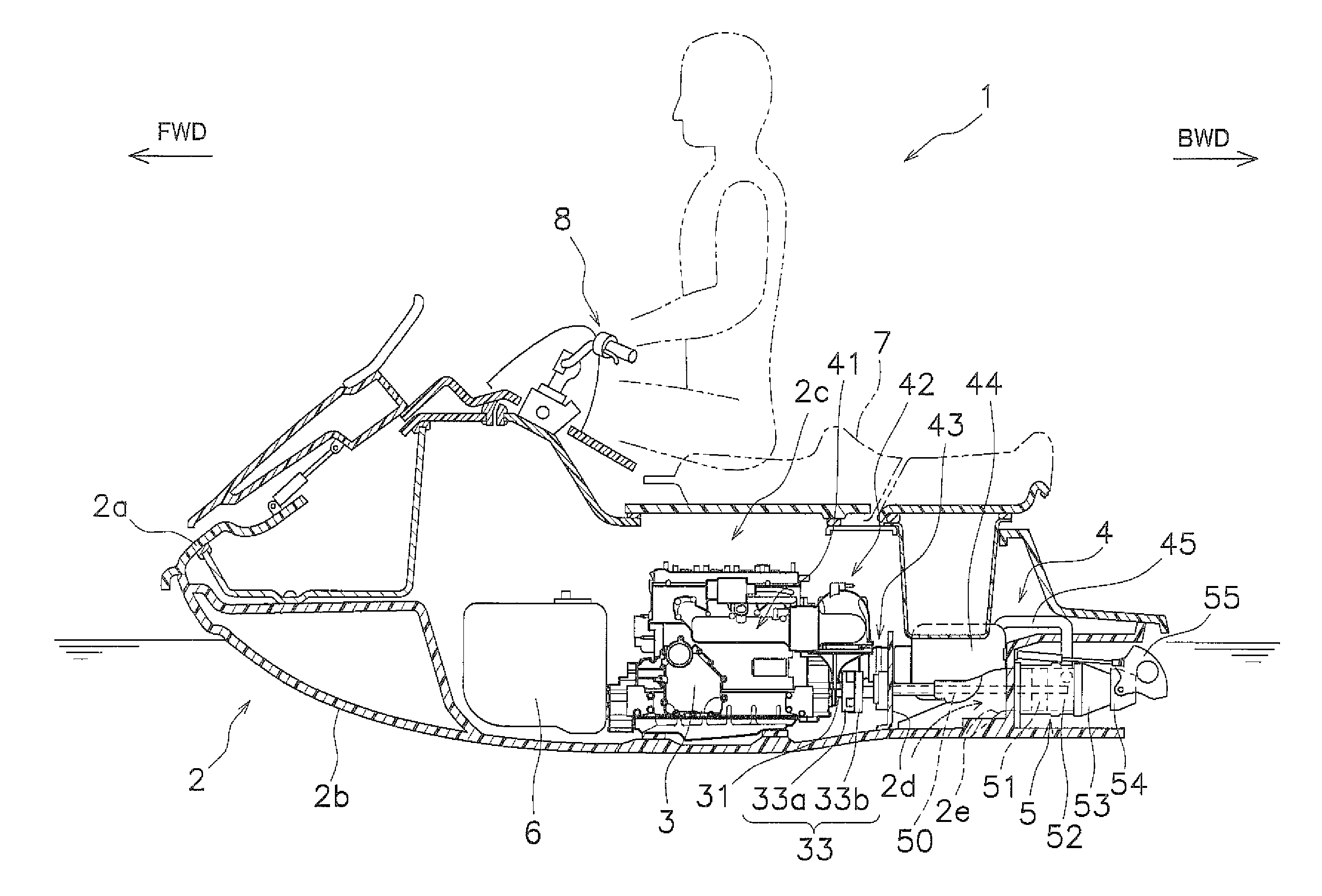
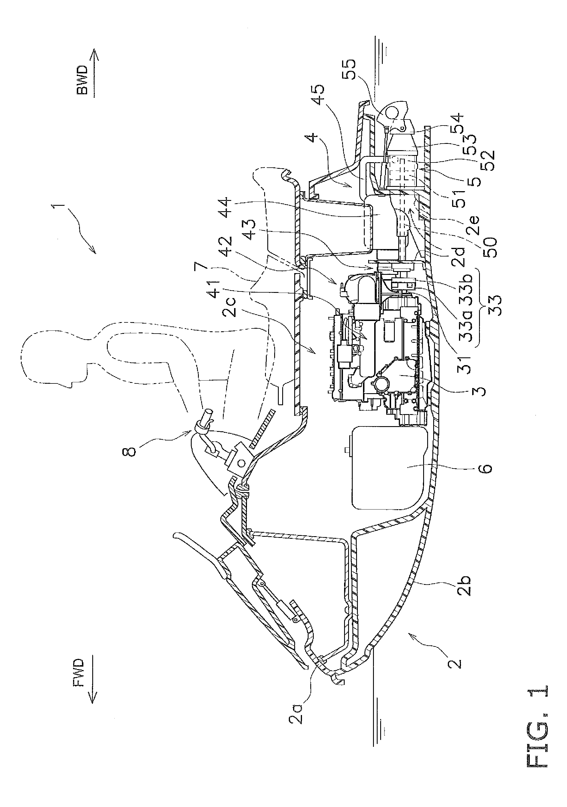
[0029]A water jet propulsion watercraft according to preferred embodiments of the present invention will now be explained with reference to the drawings. In the figures, “FWD” indicates a forward movement direction of the watercraft and “BWD” indicates a reverse movement direction of the watercraft. “W” indicates a widthwise direction, i.e., a left-right direction, of the water jet propulsion watercraft.

[0030]FIG. 1 is a sectional view showing an overall configuration of a water jet propulsion watercraft 1 according to the first preferred embodiment of the present invention. The water jet propulsion watercraft 1 preferably is a so-called personal watercraft (PWC). The water jet propulsion watercraft 1 includes a hull 2, an engine 3, an exhaust passage 4, and a jet propulsion unit 5. The hull 2 includes a deck 2a and a hull body 2b. The engine 3 is housed inside the hull 2. The jet propulsion unit 5 is driven by the engine 3. The exhaust passage 4 guides exhaust gas from the engine 3...


PUM


Abstract

A water jet propulsion watercraft includes a first exhaust pipe that is fixed to an engine and connected to an exhaust port of the engine. A damper section reduces vibrations from the engine. A catalytic converter unit is connected to the first exhaust pipe. The catalytic converter unit is attached to the engine through the damper section. A second exhaust pipe includes a first flexible pipe having a flexible quality and is connected to the catalytic converter unit. A water lock is fixed to a hull of the watercraft and connected to the second exhaust pipe.

Description

BACKGROUND OF THE INVENTION[0001]1. Field of the Invention[0002]The present invention relates to a water jet propulsion watercraft, and more specifically, to a water jet propulsion watercraft including a damper section that reduces vibrations transmitted from an engine to a catalytic converter unit.[0003]2. Description of the Related Art[0004]A water jet propulsion watercraft is conventionally provided with a catalytic converter arranged in an exhaust passage. For example, Laid-open Japanese Patent Application Publication 11-11393 discloses a water vehicle having a catalytic converter. The catalytic converter is supported on an intermediate exhaust pipe with a mounting flange. The intermediate exhaust pipe is fixed to a cylinder head of an engine with bolts.[0005]The efficiency with which a catalytic converter treats exhaust gas improves when the exhaust gas is held at a higher temperature as it passes through the catalytic converter. Consequently, it is preferable for the length of...

Claims


Application Information

Patent Timeline
Patent Type & Authority Patents(United States)
IPC IPC(8): B63H21/32F01N13/00F01N3/04F01N13/12F01N13/14F01N13/18
CPCB63H21/32F01N3/043F01N13/141F01N13/1805F01N13/12Y02T10/20Y02T10/12
Inventor MOROTA, KOICHIROOZAWA, SHIGEYUKI
Owner YAMAHA MOTOR CO LTD
Features
  • R&D
  • Intellectual Property
  • Life Sciences
  • Materials
  • Tech Scout
  • Unparalleled Data Quality
  • Higher Quality Content
  • 60% Fewer Hallucinations
Learn More