Orthopaedic implant system and fasteners for use therein

a technology which is applied in the field of orthopaedic implants and fasteners for use therein, can solve the problems of pain in the patient, prior systems of coupling components have several problems, and the components of knee implants are subject to large loads, so as to prevent spin out, improve the effect of structure and prevent the patient from falling ou

Active Publication Date: 2014-09-30
SMITH & NEPHEW INC
View PDF14 Cites 4 Cited by
  • Summary
  • Abstract
  • Description
  • Claims
  • Application Information

AI Technical Summary

Benefits of technology

[0012]Certain embodiments described herein provide an orthopaedic assembly including a tibial component and one of a fixed tibial insert or a rotatable tibial insert. The assemblies may be provided with improved structure to couple the tibial insert to the tibial component to prevent spin out, pull out, other undesired rotations and / or translations, and / or irritation to the patient's surrounding anatomy.
[0013]The tibial components described herein may include a retaining tab with a hooked edge that couples to a tab opening on an inferior surface of the tibial insert (either the fixed insert or the rotatable insert). The retaining tab may be set back from the outermost anterior edge of the tibial component such that when assembled, a portion of the tibial insert covers the retaining tab. Thus, neither the retaining tab or the tab opening are exposed to the patient's surrounding anatomy, preventing possible pinch points and irritation when the knee is in flexion. The hooked edge of the retaining tab contacts an inner surface of the tibial insert to prevent vertical separation (or pull out) of the tibial insert from the tibial component.
[0014]Certain embodiments may also be provided with structure to prevent excessive or unwanted rotation between the tibial component and the tibial insert. For example, tibial inserts may be provided with tab openings (such as the tab openings described above) that receive the retaining tab of the tibial component and are structured in a manner to limit movement of the retaining tab in the tab opening. The fixed tibial insert may be provided with a tab opening conforming in at least some dimensions to the size and shape of the retaining tab, such that there is little to no clearance with the retaining tab, thus helping to prevent rotation of the fixed tibial insert. In contrast, the rotatable tibial insert may be provided with a relatively elongated tab opening, such that there is clearance with the retaining tab. This clearance may allow the rotatable tibial insert to rotate with respect to the tibial component.
[0015]Certain embodiments may also be provided with fasteners to further minimize any movement of the fixed tibial insert. Such fasteners may include a deformable portion that creates an interference fit with the fixed tibial insert. The interference fit will help retain the fastener within the fixed tibial insert even if the fastener rotates or otherwise becomes loose.

Problems solved by technology

The components of a knee implant are subject to large loads and other forces in vivo that are applied over many cycles throughout the implant's useful life.
Prior systems of coupling the components have several problems.
First, some prior systems use coupling mechanisms that are “exposed” in that when the knee joint is in flexion, edges, protrusions or other surfaces of the coupling mechanism contact or impinge on the patient's surrounding anatomy.
Such contact or impingement may be painful to the patient, may destroy or damage the ligamenture, bone and / or other anatomy, or may damage the locking component.
Second, many prior systems do not provide adequate constraints against movement (both rotational and vertical) of tibial inserts with respect to their associated tibial components, especially as the implant is cycled numerous of times. In some instances, prior systems can fail when the tibial insert “spins outs,”“pulls out,” or otherwise becomes dislocated with respect to the tibial component.
Spin out refers to excessive rotation of the tibial insert (particularly for rotatable tibial inserts) such that the tibial insert becomes improperly oriented within the knee joint.
Third, prior systems with fixed tibial inserts, in some instances, may undesirably allow at least some rotation of the fixed insert.
Fourth, prior systems with fixed tibial inserts may use fasteners to secure the insert to the tibial component that may loosen and back out, thus un-coupling the insert from the tibial component.
Such fasteners may include a deformable portion that creates an interference fit with the fixed tibial insert.

Method used


Image

  • Orthopaedic implant system and fasteners for use therein
  • Orthopaedic implant system and fasteners for use therein
  • Orthopaedic implant system and fasteners for use therein

Examples


Embodiment Construction

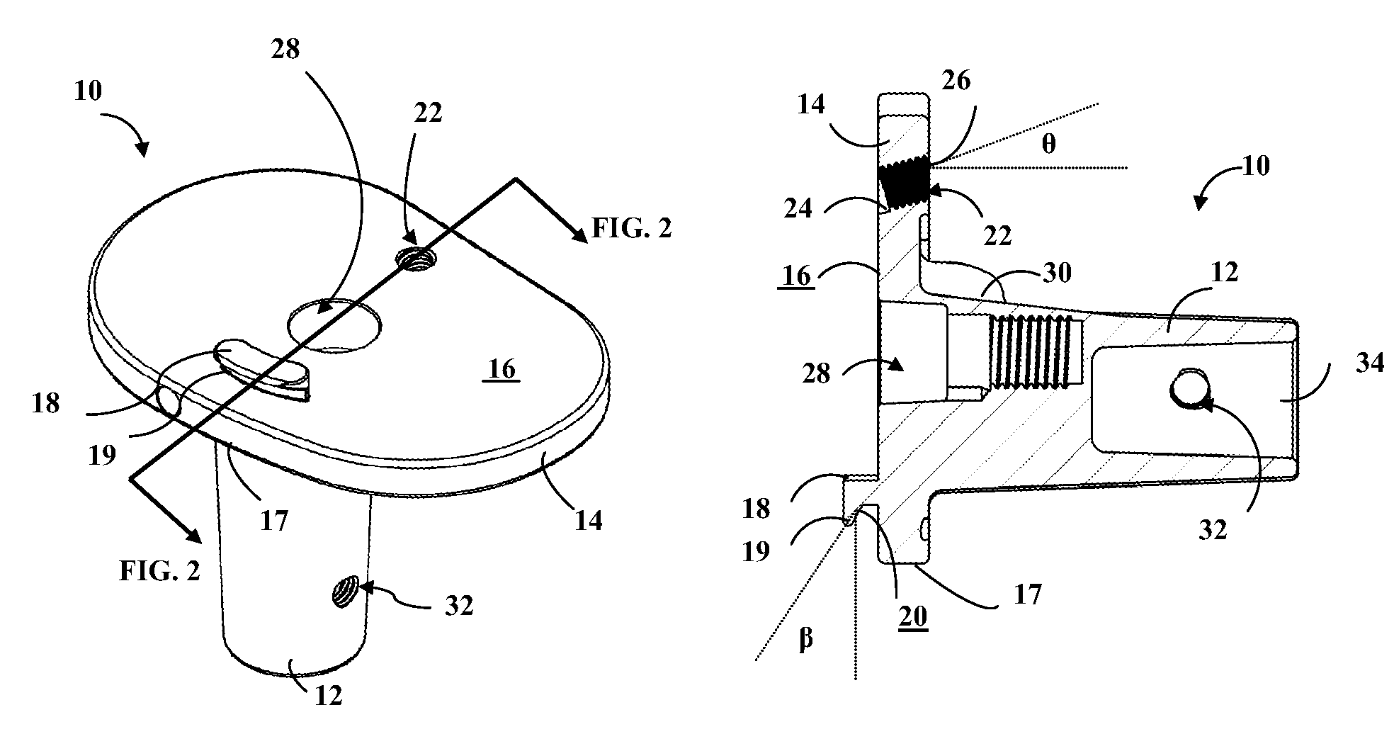
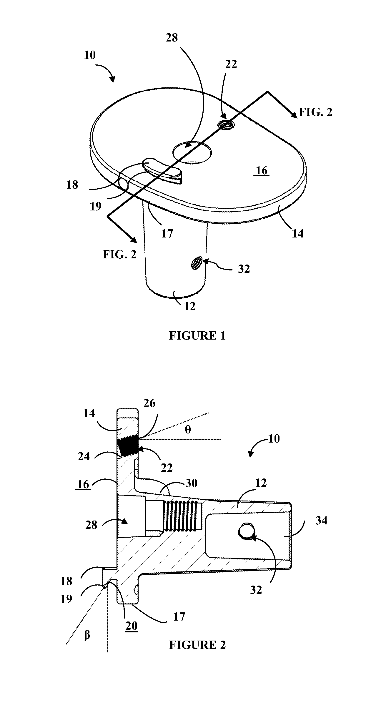
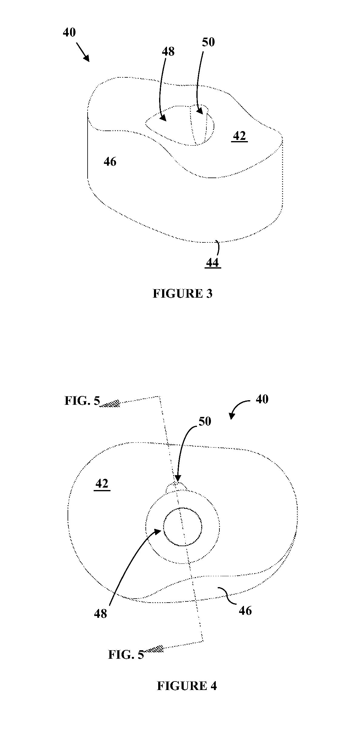
[0064]FIGS. 1-23 illustrate structures and mechanisms for coupling tibial inserts and tibial components together. Although the orthopaedic implants shown and described herein are for knee joints, the same concepts could potentially be applied to implants for other joints or orthopaedic implants. FIGS. 3-16 illustrate embodiments of implants that include fixed tibial inserts 40 or other types of fixed constructs, whereas FIGS. 17-23 illustrate embodiments that include rotatable tibial inserts 90. In the embodiments shown, the same tibial component 10 may be used, thus providing for interchangability between tibial inserts 40, 90.

[0065]FIGS. 1-2 show a tibial component 10 including a stem portion 12 and a tibial tray 14. The stem portion 12 may be dimensioned to couple with structure (not shown) that is inserted into a patient's intramedullary canal (and itself may be inserted into the intramedullary canal). Thus, for example, the stem portion 12 may include at least one opening 32 an...


PUM


Abstract

Orthopaedic assemblies including a tibial component and one of a fixed tibial insert or a rotatable tibial insert. The assemblies may include structure to prevent undesired movement between the tibial component and insert. For example, a retaining tab may be provided on the tibial component that couples to a tab opening on a surface of the tibial insert (either the fixed or rotatable insert). When assembled, the retaining tab may be covered to avoid possible irritation to the patient's surrounding anatomy. The fixed tibial insert may be provided with a tab opening that provides a minimal amount clearance with the retaining tab to help prevent rotation of the fixed tibial insert. The rotatable tibial insert may be provided with a tab opening with more clearance with the retaining tab to allow at least some rotation with the tibial component.

Description

CROSS REFERENCE TO RELATED APPLICATIONS[0001]This application claims the benefit of U.S. Provisional Patent Application Ser. No. 61 / 350,346 entitled “Orthopaedic Implant System and Fasteners for use Therein” and filed Jun. 1, 2010, the entire contents of which are hereby incorporated by this reference.RELATED FIELDS[0002]Apparatus and methods for coupling components of orthopaedic implants together are described herein.BACKGROUND OF THE INVENTION[0003]Orthopaedic implants, including for instance knee implants, can be modular in nature and include several components. For instance, many knee implants include a femoral implant and a tibial implant. The tibial implant may include a base tibial component and one or more inserts. After bone resectioning, the tibial component is positioned on the patient's tibia and the femoral component is positioned on the patient's femur. The tibial insert is secured to or captured by the tibial component, and includes a superior surface for contact wit...

Claims


Application Information

Patent Timeline
Patent Type & Authority Patents(United States)
IPC IPC(8): A61F2/38A61F2/28A61F2/30
CPCA61F2/3868A61F2/389A61F2/3886A61F2002/2892A61F2002/3051A61F2002/30528A61F2002/30518A61F2002/30507
Inventor DEES, JR., ROGER RYANCRABTREE, JR., PAUL CHARLES
Owner SMITH & NEPHEW INC
Why Eureka
Try Eureka