Filter

a filter and filter technology, applied in the field of filters, can solve the problem of increasing the size of the multi-layer dielectric filter b>500/b>

Active Publication Date: 2014-09-30
MURATA MFG CO LTD
View PDF7 Cites 2 Cited by
  • Summary
  • Abstract
  • Description
  • Claims
  • Application Information

AI Technical Summary

Benefits of technology

[0011]Accordingly, preferred embodiments of the present invention provide a filter that can narrow the pass frequency band without being increased in size.
[0014]According to various preferred embodiments of the present invention, a pass frequency band can be narrowed without increasing the size of a filter.

Problems solved by technology

However, there is a problem in that, if it is attempted to narrow the pass frequency band, the size of the multilayer dielectric filter 500 is increased.

Method used


Image

  • Filter
  • Filter
  • Filter

Examples


Embodiment Construction

[0022]Hereafter, a filter according to preferred embodiments of the present invention will be described.

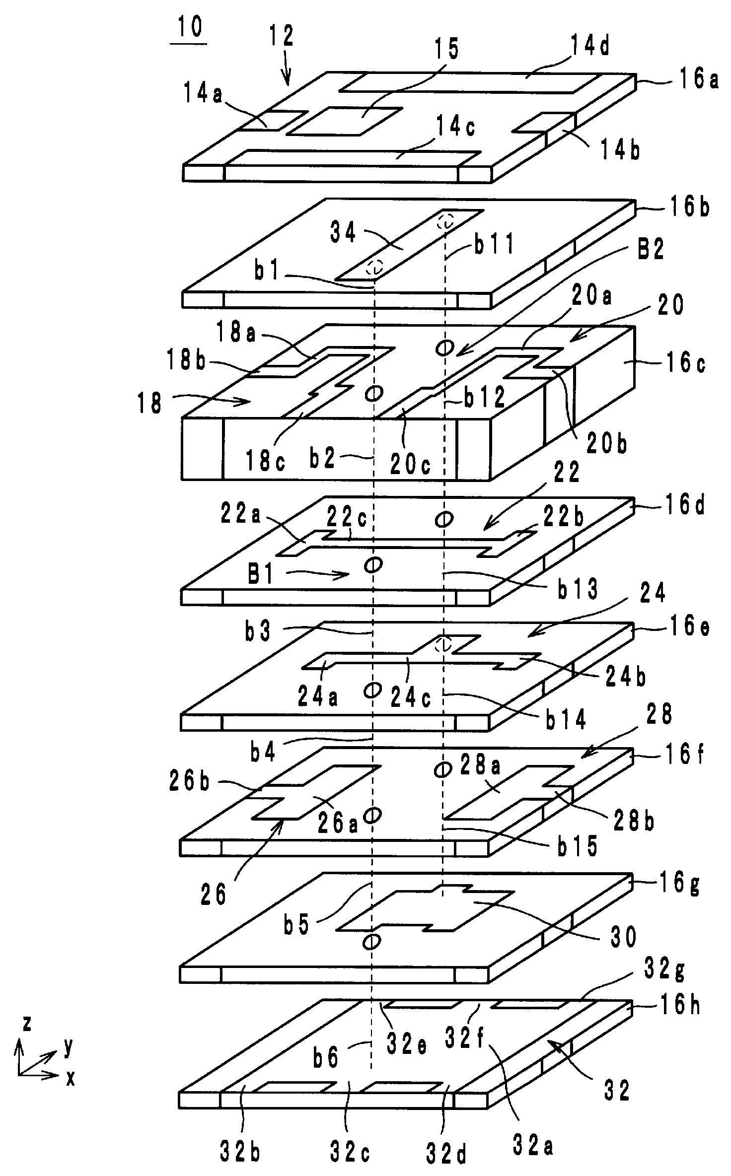
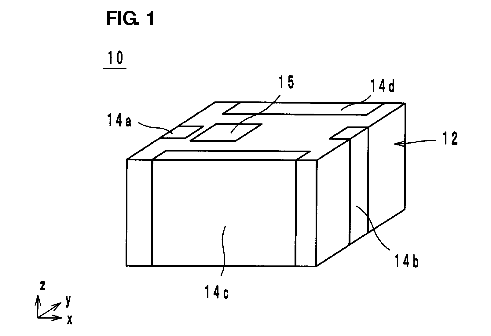
[0023]FIG. 1 is an external perspective view of a filter 10 according to a preferred embodiment of the present invention. FIG. 2 is an exploded perspective view of the filter 10. FIG. 3 is an equivalent circuit diagram of the filter 10. A z-axis direction indicates the stacking direction in FIG. 1 and FIG. 2. In addition, an x-axis direction indicates a direction parallel to long sides of the filter 10 when viewed in plan from the z-axis direction. A y-axis direction indicates a direction parallel to short sides of the filter 10 when viewed in plan from the z-axis direction. The origin of the x axis, the y axis and the z axis is the center of the filter 10.

[0024]As illustrated in FIG. 1 and FIG. 2, the filter 10 includes a multilayer body 12, outer electrodes 14 (14a to 14d), a direction recognition mark 15, resonators LC1 to LC3 and capacitors C4 to C7. As illustrated in FIG. 2, ...


PUM


Abstract

A filter includes a multilayer body including a plurality of insulator layers stacked on top of one another. Outer electrodes are provided on surfaces of the multilayer body. A first resonator is connected to a first one of the outer electrodes and includes a first coil. A second resonator is connected to a second one of the outer electrodes and includes a second coil. A third resonator includes a third coil that is magnetically coupled with the first and second coils. The first and second coils are respectively defined by coil conductor layers provided on an insulator layer. The third coil is defined by via hole conductors that penetrate through the insulator layer in a z-axis direction.

Description

BACKGROUND OF THE INVENTION[0001]1. Field of the Invention[0002]The present invention relates to filters and more specifically relates to multilayer LC filters.[0003]2. Description of the Related Art[0004]A multilayer dielectric filter described in Japanese Unexamined Patent Application Publication No. 2006-33614 is an example of a known conventional filter. Hereafter, the multilayer dielectric filter described in Japanese Unexamined Patent Application Publication No. 2006-33614 will be described with reference to the drawings. FIG. 6 is an exploded perspective view of a multilayer dielectric filter 500.[0005]The multilayer dielectric filter 500 includes a multilayer body 502 and outer electrodes 503 (503a to 503d). The multilayer body 502 has a rectangular parallelepiped shape and is formed by stacking rectangular insulator layers 504 (504a to 504j) on top of one another. The outer electrodes 503 are respectively provided on the four side surfaces of the multilayer body 502. The ou...

Claims


Application Information

Patent Timeline
Patent Type & Authority Patents(United States)
IPC IPC(8): H03H7/09H03H1/00H03H7/01H03H7/075
CPCH03H7/1775H03H7/0115H03H7/1708H03H2001/0085H03H7/075H03H7/09H03H7/1766
Inventor MASUDA, HIROSHIMORI, TAKAHIRO
Owner MURATA MFG CO LTD
Why Eureka
Try Eureka