Sonic drill head

a sonic drill and head technology, applied in vibration drilling, directional drilling, portable percussive tools, etc., can solve the problems of not being able to effectively rotate the spindle, existing sonic drill heads do not currently allow the passage of downhole instruments, and existing sonic drill heads do not currently allow the passage of existing sonic drill heads

Active Publication Date: 2014-10-07
LAYNE CHRISTENSEN COMPANY
View PDF28 Cites 5 Cited by
  • Summary
  • Abstract
  • Description
  • Claims
  • Application Information

AI Technical Summary

Benefits of technology

[0006]The sine generator is configured to support the spindle within the housing such that the spindle is free to rotate about the spindle axis relative to the sine generator, yet the sine generator still transfers the linear sinusoidal force to the spindle along the spindle's axis of rotation. The sine generator is configured to allow the spindle to pass through the sine generator and the spindle may protrude outside the outer housing in some embodiments. This configuration allows the spindle to rotate both at low speeds used for sonic drilling and high speeds used for diamond core or other rotary drill methods. Further, an embodiment of the present invention includes the spindle being a continuous and hollow tube section allowing the introduction or removal of drilling fluid, mud, cuttings, and / or tooling, or other drilling aids into or out of the drill string through the top of the spindle.

Problems solved by technology

Sonic drill heads known in the art do not efficiently provide the ability to rotate the spindle at high speeds without vibration such that the drill head can additionally perform traditional diamond core or other rotary drilling methods.
The passage of materials through the spindle to or from the drill string is generally not a consideration in sonic drill heads currently in use because the slow rotation of sonic drilling does not generally generate the same drilling conditions of other higher speed rotary drilling methods that often require passage of materials through the drill string to aid in the drilling process.
As a result, existing sonic drill heads do not currently allow the passage of cuttings through the top of the drill head that are desirable when performing deep drilling.
Further, existing sonic drill heads do not currently allow the passage of downhole instrumentation, and / or tooling through the top of the drill head which may be desirable when monitoring downhole conditions while drilling.

Method used


Image

  • Sonic drill head
  • Sonic drill head
  • Sonic drill head

Examples


Embodiment Construction

[0018]The following detailed description of the invention references the accompanying drawing figures that illustrate specific embodiments in which the invention can be practiced. The embodiments are intended to describe aspects of the invention in sufficient detail to enable those skilled in the art to practice the invention. Other embodiments can be utilized and changes can be made without departing from the scope of the present invention. The present invention is defined by the appended claims and the description is, therefore, not to be taken in a limiting sense and shall not limit the scope of equivalents to which such claims are entitled.

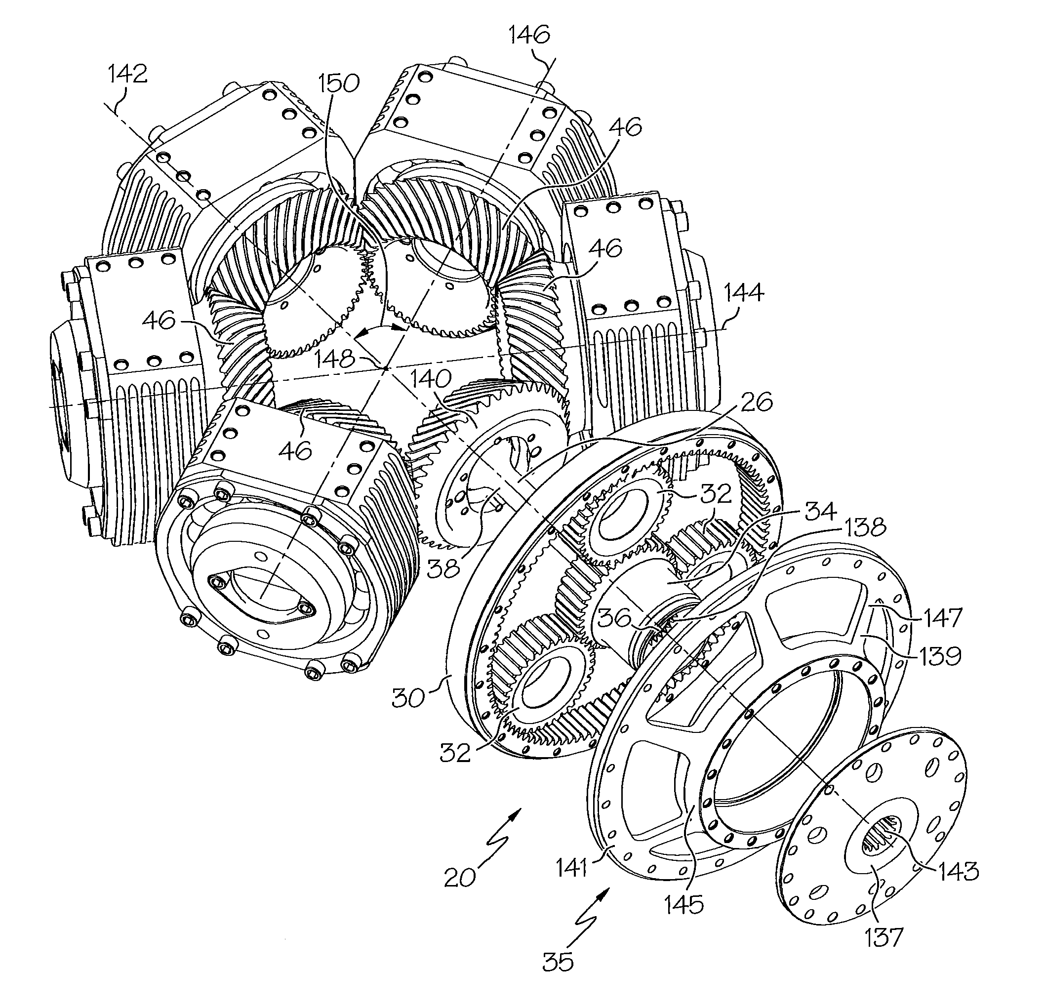
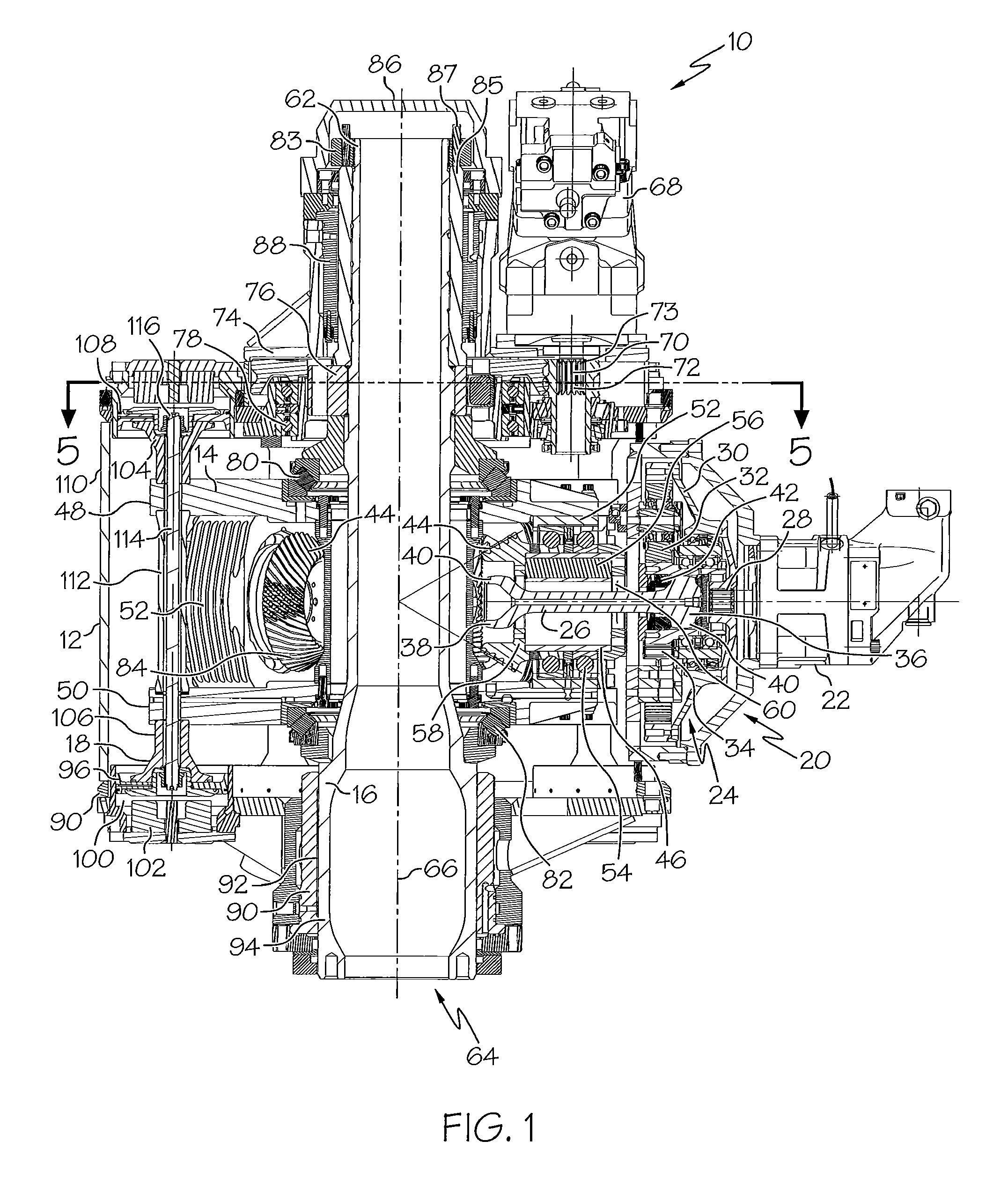
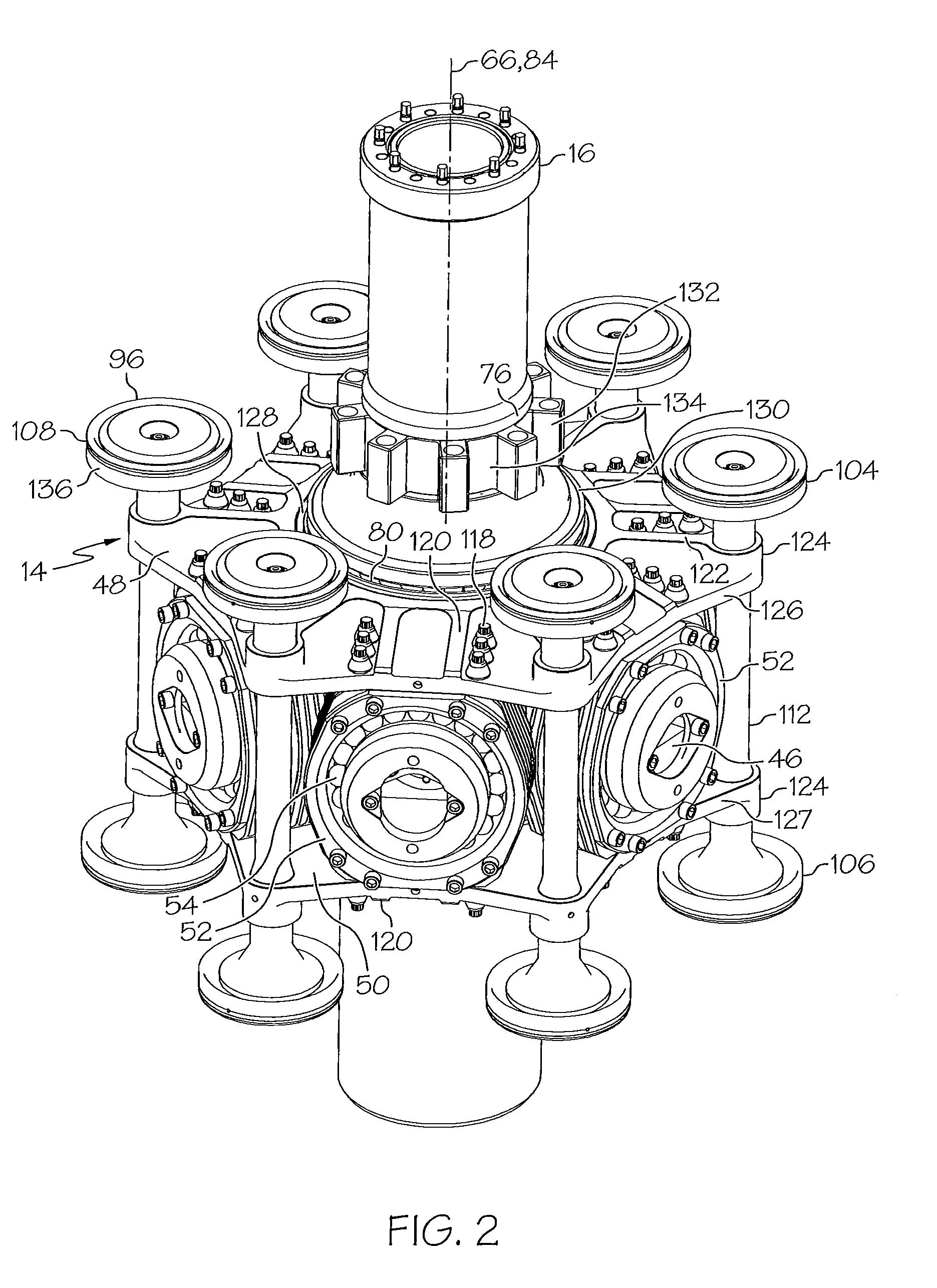
[0019]Now turning to FIG. 1, a sonic drill head 10 comprises an outer housing 12, a sine generator 14, a spindle 16, and an isolation system 18. Outer housing 12 generally encloses the other components of sonic drill head 10 including sine generator 14, spindle 16 and isolation system 18. An embodiment of outer housing 12 may be assembled such...


PUM


Abstract

A sonic drill head comprising an outer housing, an isolation system, a sine generator and a spindle. The sine generator generates a linear sinusoidal vibration force through the rotation of a plurality of eccentric masses. The sine generator is configured to translate the linear sinusoidal force to the spindle in a direction corresponding to the spindle's axis of rotation. The sine generator supports the spindle within the housing such that the spindle is free to rotate about the spindle axis. The spindle is generally a hollow tube section thereby allowing the passage of drilling fluid, mud, cuttings, and / or tooling. The isolation system generally reduces the transfer of the vibration force generated by the sine generator to the outer housing, yet is able to transfer an applied thrust force from the outer housing to the sine generator.

Description

CROSS-REFERENCE TO RELATED APPLICATIONS[0001]None.BACKGROUND OF THE INVENTION[0002]The present invention is generally directed to a sonic drill head. Sonic drill heads generally impart a vibratory force and send high frequency resonant vibrations down a drill string to a drill bit. The sonic drill head combines this vibratory force with a slow rotation of the drill string to ensure that the energy applied and wear resulting from drilling are evenly distributed at the drill face. Vibration generators for sonic drilling may be housed with a rotary drive or may be a stand alone component of a drill string. The frequency of vibration is generally between 50 and 120 hertz (cycles per second) and the drill operator controls the frequency of the vibrations to match the natural frequency of the drill string to take advantage of the resonance effects of the drill string and / or to suit the specific conditions of the soil / rock geology. The resonance created at the selected frequency magnifies ...

Claims


Application Information

Patent Timeline
Patent Type & Authority Patents(United States)
IPC IPC(8): E21B7/24
CPCE21B7/24
Inventor SMITH, BRIANZAHARIEV, KRASIMIRJONES, KYLE
Owner LAYNE CHRISTENSEN COMPANY
Why Eureka
Try Eureka