RFID (radio frequency identification) tag

a radio frequency identification and tag technology, applied in the field of rfid (radio frequency identification) tags, can solve the problems of electromagnetic wave interference or absorbed, electromagnetic wave gain is too low, circuit inside cannot be driven, etc., to prevent the reading ability of rfid tags from being affected, and increase the signal strength of driving signals.

Inactive Publication Date: 2014-10-07
LIN CHIN HUA
View PDF6 Cites 8 Cited by
  • Summary
  • Abstract
  • Description
  • Claims
  • Application Information

AI Technical Summary

Benefits of technology

[0015]Therefore, the main object of the present invention is to provide an RFID tag including an electric or magnetic field coupling casing, which cooperates with a grounding casing to induce a resonant electromagnetic field there-between so as to enhance the signal strength of electromagnetic wave signals.
[0018]The RFID (Radio Frequency Identification) module is installed within the coupling space defined between the coupling part and the grounding casing. The RFID module includes an RFID (Radio Frequency Identification) chip and a coupling member coupled electrically to the RFID chip for reception of the driving signal and transmission of the identification signal. Upon receiving the wave of the driving signal and the identification signal, surface current is generated on an upper surface of the RFID tag, which, in turn, induces a resonant electromagnetic field within the coupling space, thereby enhancing the detecting strength of the RFID (Radio Frequency Identification) module relative to the one of the driving signal and the identification signal.
[0021]In one embodiment of the present invention, the covering part of the coupling casing is connected electrically to the grounding casing via a plurality of wires. In another embodiment of the present invention, the RFID tag further includes an insulating case installed between the coupling casing and the grounding casing. Preferably, the insulating case includes a plastic material, which prevents the problem that the enhanced electric field can not be generated due to electric conductance caused by objects contacting the coupling part and the grounding casing once the objects are stacked over one another and thus prevents the reading ability of the RFID tag from being affected.
[0022]When compared with the conventional RFID tag with additional layers to absorb reflecting wave or the conventional ceramic capacitor with micro-stripe antennas, the RFID tag of the present invention increases the signal strength of the driving signal or the identification signal by providing the coupling casing for inducing and generating the resonant electromagnetic field between the coupling casing and the grounding casing once the wave of the driving signal or the identification signal is received. As a result, the RFID tag of the present invention provides a larger reading range; in embodiments such as the RFID tag is applied in stacked metal objects, it remains readable even when only few driving signal or identification signal are received. Besides, since the thickness of the coupling casing does not affect the generation of the resonant electromagnetic field, nor the reading ability of the RFID tag, the RFID tag of the present invention can be reinforced by adding the thickness of the coupling casing so that the RFID tag has better crashworthiness.

Problems solved by technology

Among them, passive RFID tags are not built in with a power supply and the circuit inside can only be driven via the received energy of electromagnetic wave outside.
However, passive RFID tags in the prior art are planar RFID tags on the basis of dipole antennas; gain of its receiving and transmitting signals is too low and is affected easily by the environment.
When the UHF RFID tag is applied on surfaces of metal, liquid or earth, the electromagnetic wave will be highly and seriously interfered or will be absorbed.
The phenomena may cause the RFID chip lacks of power to get driven.
Even there is enough power to drive the chip, the same phenomena may have not enough power backscatter to the reader.
As a result, the RFID tag can only be read from its front side.
Hence, the conventional way can not satisfy the market needs and can not really solve the problem.
However, since the quality factor as its central frequency divided to bandwidth of this conventional RFID tag is very high, the RFID tag usually can only be applied in a range of narrow-bandwidth.
The matching circuit is easily affected by the ambient objects, such as metal so that the conventional RFID tag does not satisfy the market needs.
Obviously, the electromagnetic wave signals for reading the RFID tags are mostly interfered, reflected and absorbed, and the RFID tags are also likely to be damaged, which make it difficult to read the RFID tags.

Method used


Image

  • RFID (radio frequency identification) tag
  • RFID (radio frequency identification) tag
  • RFID (radio frequency identification) tag

Examples


Embodiment Construction

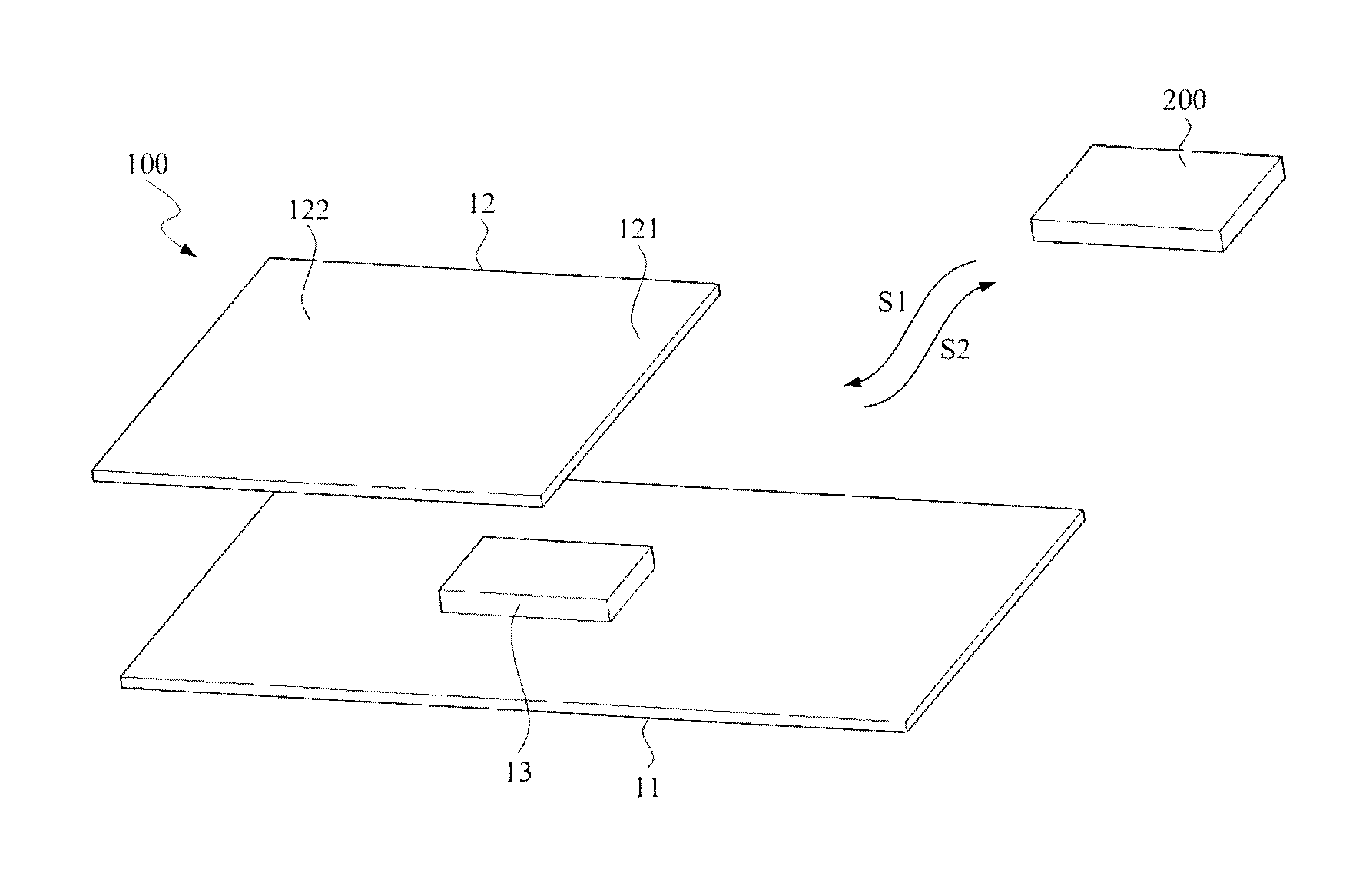
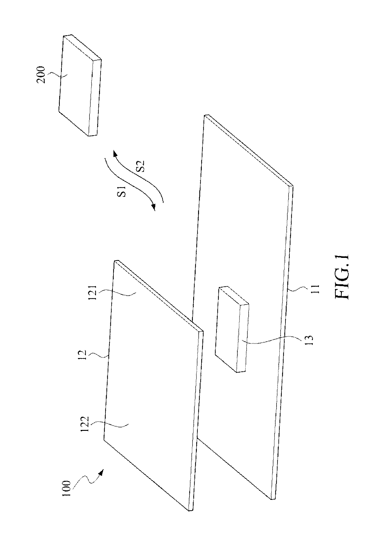
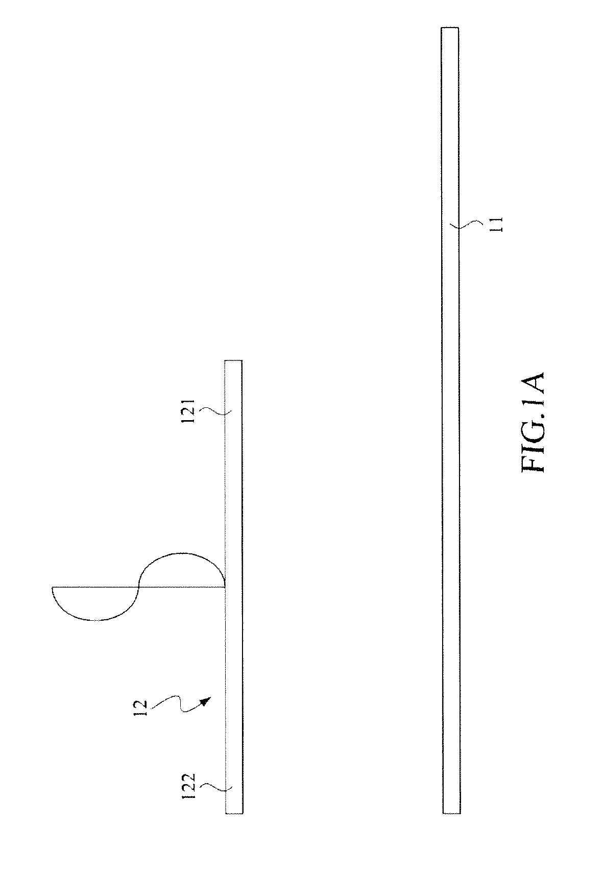
[0038]The present invention relates to an RFID (Radio Frequency Identification) tag, and more particularly, relates to an RFID tag including an electric or magnetic field coupling casing. Preferred embodiments of the present invention are disclosed in the following paragraphs for better understanding of the present invention. However, the scope of the present invention should not be limited only to the structure of the disclosed embodiments.

[0039]Referring to FIGS. 1˜5, wherein FIG. 1 is a perspective view of the first embodiment of an RFID tag according to the present invention; FIG. 1A is a lateral side view of the first embodiment of the RFID tag according to the present invention while FIG. 5 is a circuit diagram of an RFID (Radio Frequency Identification) module employed in the RFID tag according to the present invention. The RFID tag 100 is used for receiving the driving wave with a command signal S1 and backscattering the wave carrying an identification signal S2 to an RFID r...


PUM


Abstract

An RFID (Radio Frequency Identification) tag includes a grounding casing, an coupling casing disposed opposite to the grounding casing and an RFID module. The coupling casing includes a coupling part cooperating with the grounding casing to define a coupling space there-between. The RFID module is disposed in the coupling space and includes an RFID chip and a coupling member coupled electrically to the RFID chip such that upon receipt of one of the driving signal and the identification signal, surface current is generated on an upper surface of the RFID tag, which, in turn, induces a resonant electromagnetic energy within the coupling space, thereby increasing a detecting strength of the RFID module relative to the one of the driving signal and the identification signal.

Description

CROSS-REFERENCE TO RELATED APPLICATION[0001]This application is a Continuation-in-Part of U.S. patent application Ser. No. 13 / 097,319, which was filed on Apr. 29, 2011, and is currently pending.BACKGROUND OF THE INVENTION[0002]1. Field of the Invention[0003]The present invention relates to an RFID (Radio Frequency Identification) tag, and more particularly, relates to an RFID tag including an electric or magnetic field coupling casing.[0004]2. Description of the Prior Art[0005]The technology of radio frequency identification (hereafter: RFID), also called electronic tag, is a communications technology for identifying a certain target and reading / writing related data via radio signal. One of the advantages of the technology of RFID is that targets are identifiable without mechanical or optical contacts.[0006]The technology of RFID includes two parts: one is an RFID reader and the other is an RFID tag. The RFID reader is for transmitting electromagnetic wave signals to the RFID tag; a...

Claims


Application Information

Patent Timeline
Patent Type & Authority Patents(United States)
IPC IPC(8): G06K19/06G06K19/077
CPCG06K19/07771G06K19/07794
Inventor LIN, CHIN HUA
Owner LIN CHIN HUA
Why Eureka
Try Eureka