Shielding socket with two pieces housing components

a shielding socket and housing technology, applied in the direction of coupling protective earth/shielding arrangement, coupling device connection, electrical apparatus construction details, etc., can solve the problems of affecting the quality of signal transmission between the cpu, the density of the pads of the cpu and the printed circuit board becomes more and more dense, and the size of the electrical connector becomes smaller and smaller. , to achieve the effect of better shielding results

Inactive Publication Date: 2014-10-07
HON HAI PRECISION IND CO LTD
View PDF174 Cites 41 Cited by
  • Summary
  • Abstract
  • Description
  • Claims
  • Application Information

AI Technical Summary

Benefits of technology

[0007]Accordingly, an object of the present invention is to provide an electrical connector getting better shielding result.

Problems solved by technology

With the development of the electronic technology, the size of the electrical connector becomes smaller and smaller, and the density of the pads of the CPU and the printed circuit board becomes more dense and dense.
So, the electromagnetic interference between the adjacent contacts become serious and it affects the quality of the signal transmission between the CPU and the printed circuit board.
Due to the metal shielding plate is inserted between the contacts, and a space between the contacts is small, so, it is hard to produce the socket body.

Method used


Image

  • Shielding socket with two pieces housing components
  • Shielding socket with two pieces housing components
  • Shielding socket with two pieces housing components

Examples


Embodiment Construction

[0016]Reference will now be made to the drawings to describe the present invention in detail.

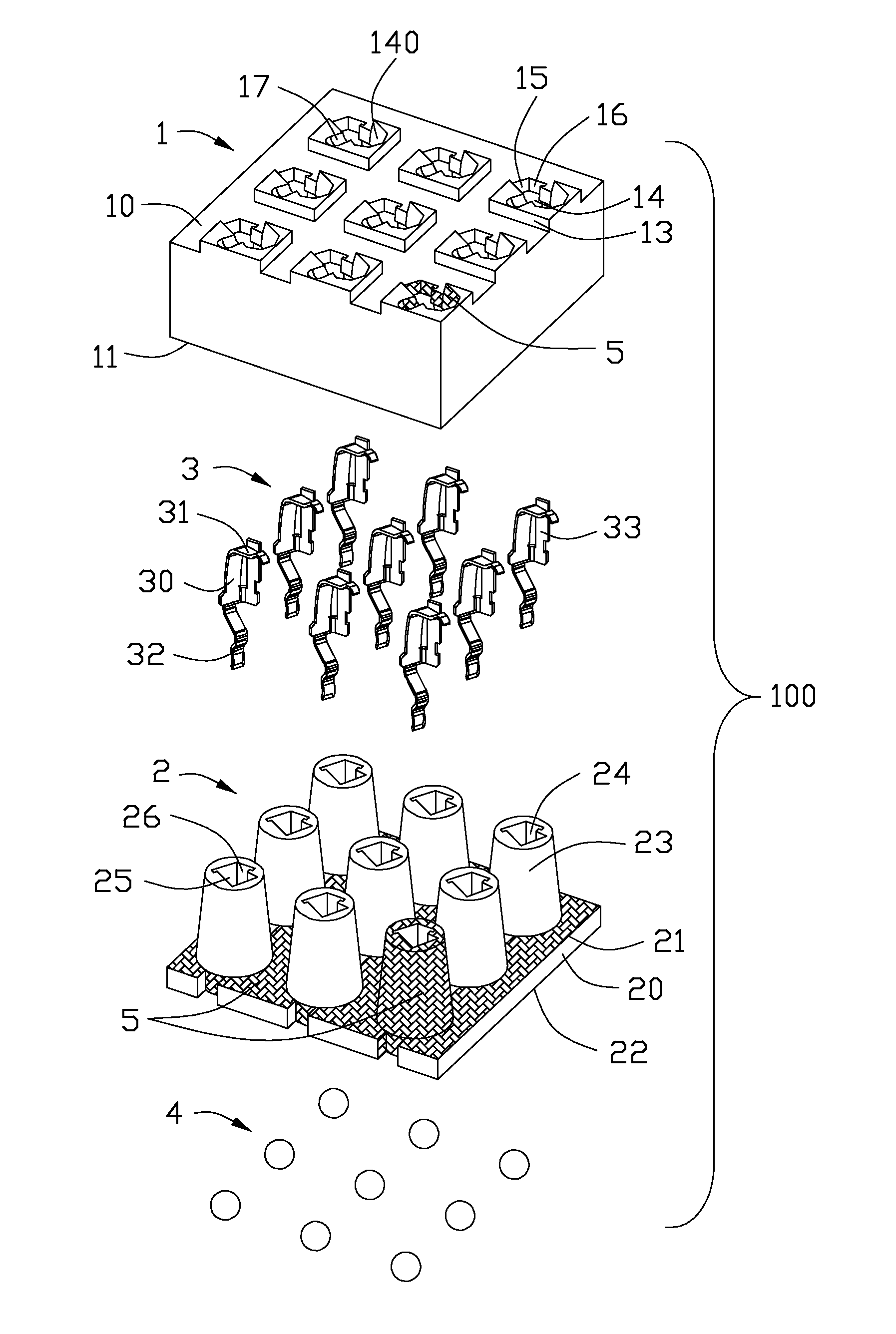
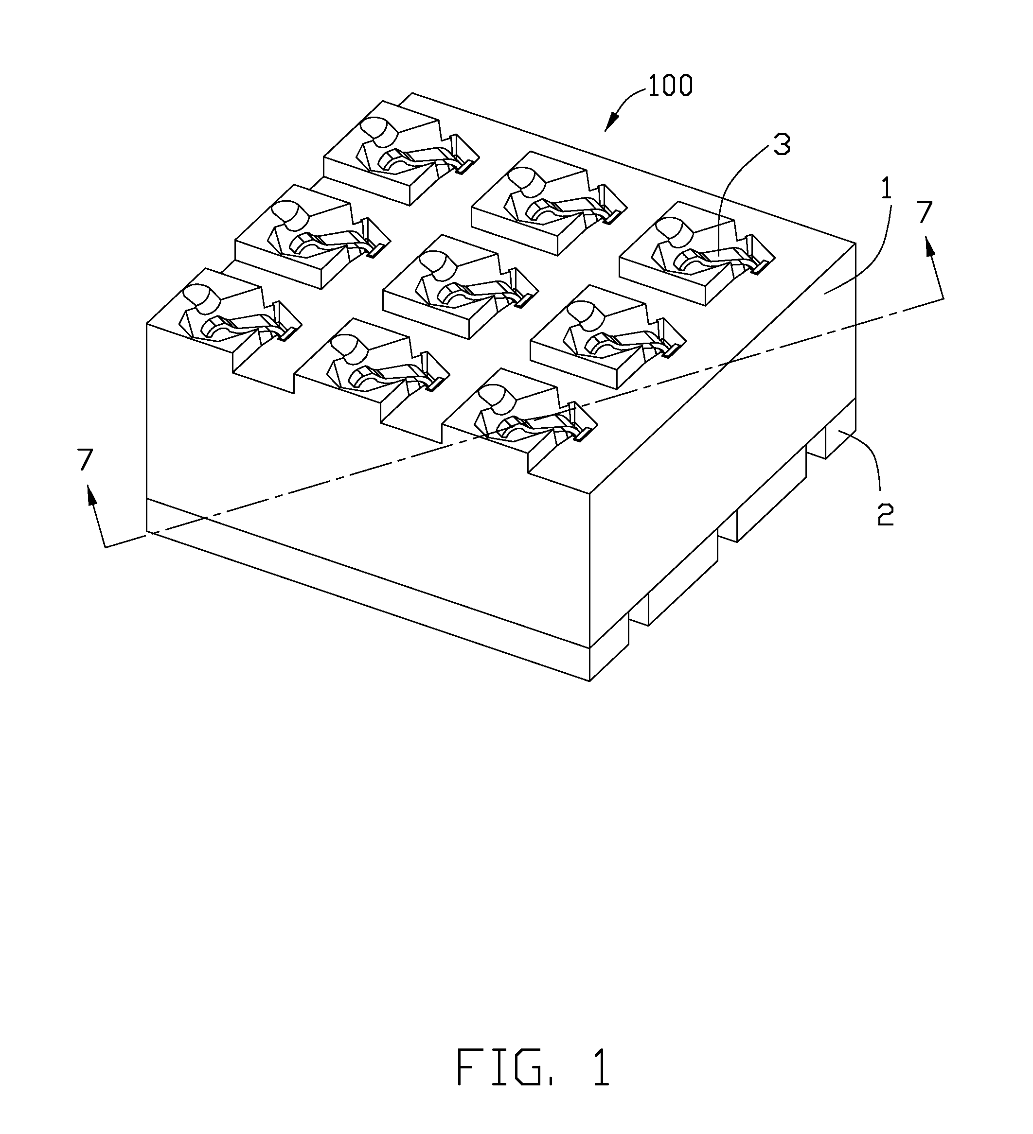
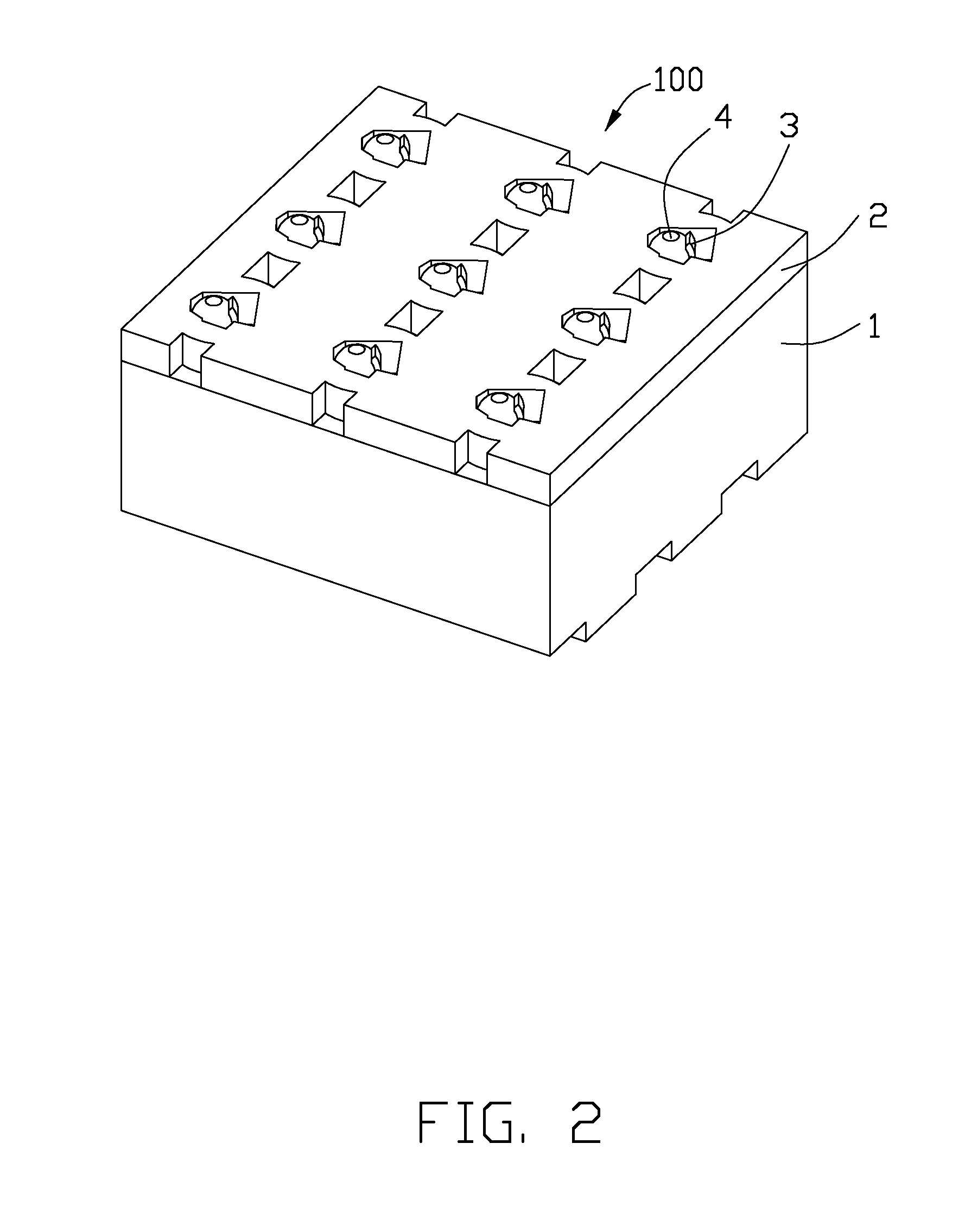
[0017]Referring to FIGS. 1-7, an electrical connector 100 according to the present invention is used to electrically connecting a chip module (not show) to a printed circuit board (not show). The electrical connector 100 comprises an insulative housing, a plurality of terminals 3 received therein and a plurality of solder balls 4 soldered to the printed circuit board. The insulative housing comprises a lower component or a secondary housing 2, and an upper component or a primary housing 1 stacked on the lower component 2.

[0018]Referring to FIGS. 3 and 5-6, the upper component 1 comprises a top surface 10 and a bottom surface 11 opposite to the top surface 10. The bottom surface 11 depresses to form a plurality of matching holes 12. Each of the matching holes 12 is configured to a taper shape and the diameter of the matching hole 12 becomes smaller and smaller from bottom to top. The top surf...


PUM


Abstract

An electrical connector for electrically connecting a chip module with a printed circuit board includes an insulative housing and a number of contacts fixed in the insulative housing. The insulative housing includes an upper component and a lower component cooperated with the upper component. The upper component has a protruding portion and the lower component has a hole cooperated with the protruding portion. The protruding portion is in touch with the hole and the contacting area is plated with a metal fillings. It is easy to assemble and it has better shielding effects.

Description

BACKGROUND OF THE INVENTION[0001]1. Field of the Invention[0002]The present invention relates to an electrical connector, and more particularly to an electrical connector mounted to a printed circuit board for receiving an Integrated Circuit package.[0003]2. Description of the Prior Art[0004]As the “Nonlinear Analysis Helps Design LGA Connectors” (Connector Specifier, February 2001) show, an electrical connector includes a base and a number of contacts assembled in the base. An upper contacting points of the terminals contact with a CPU and a lower contacting points of the terminals contact with a printed circuit board, and formed the signal transmission between the CPU and the printed circuit board. With the development of the electronic technology, the size of the electrical connector becomes smaller and smaller, and the density of the pads of the CPU and the printed circuit board becomes more dense and dense. So, the electromagnetic interference between the adjacent contacts beco...

Claims


Application Information

Patent Timeline
Patent Type & Authority Patents(United States)
IPC IPC(8): H01R12/00H01R12/71H01R13/6599H05K7/10
CPCH01R12/71H01R12/716H01R13/6599H05K7/10H05K7/1069
Inventor CHANG, YEN-CHIHCHEN, KE-HAO
Owner HON HAI PRECISION IND CO LTD
Why Eureka
Try Eureka