
Dielectric ceramic composition and electronic device

a technology of ceramic composition and electronic device, which is applied in the direction of inorganic chemistry, niobium compounds, fixed capacitors, etc., can solve the problems of ferroelectricity of ceramic composition, reduced effective capacitance under used environment, and rapid reduction of specific permittivity, so as to reduce specific permittivity and improve the effect of properties

Active Publication Date: 2014-10-07
TDK CORPARATION
View PDF6 Cites 11 Cited by
  • Summary
  • Abstract
  • Description
  • Claims
  • Application Information

AI Technical Summary

Benefits of technology

[0017]Note that the above compound shows relatively low specific permittivity when field intensity is low (e.g. when direct current is not superimposed). However, said compound is paraelectric and that there is little decline in its specific permittivity even when field intensity increases, which differs from ferroelectrics of barium titanate and the like. Therefore, under a high field intensity, dielectric ceramic composition of the invention show better characteristics (e.g. DC-Bias characteristic) than ferroelectrics.
[0018]In addition, dielectric ceramic composition of the present invention comprises an oxide of “M”. Sintering property of dielectric ceramic composition of the present invention can be improved by including such oxide. As a result, dielectric ceramic composition of the present invention will be sufficiently sintered; and will be effective to improve moisture resistance property and to prevent structural deficiency.

Problems solved by technology

However, when electronic device having dielectric layer of ferroelectrics is used under a high rated voltage, namely, when it is used under a high field intensity, various problems due to ferroelectricity of the ceramic composition were caused.
For instance, there was a problem that specific permittivity rapidly decreases as field intensity increases; and as a result, effective capacitance under used environment decreases.
In addition, there were problems that capacitance of capacitor decreases as specific permittivity of dielectrics decreases, which leads to deterioration of DC-Bias characteristic, and cracks or noises due to electrostriction generate.
There was also a problem such as a deterioration of capacitance change rate with respect to temperature.
In addition, sintering may be insufficient during firing process to obtain ceramic composition; and moisture resistance could have been deteriorated or structural deficiency could have been occurred.

Method used


Image

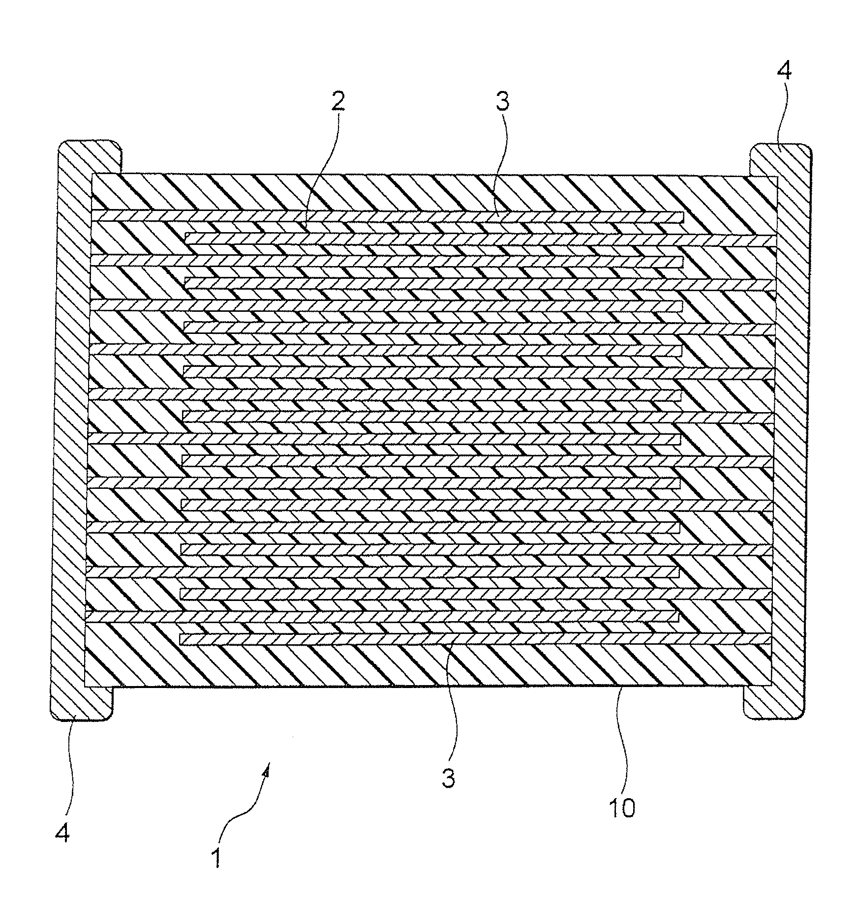
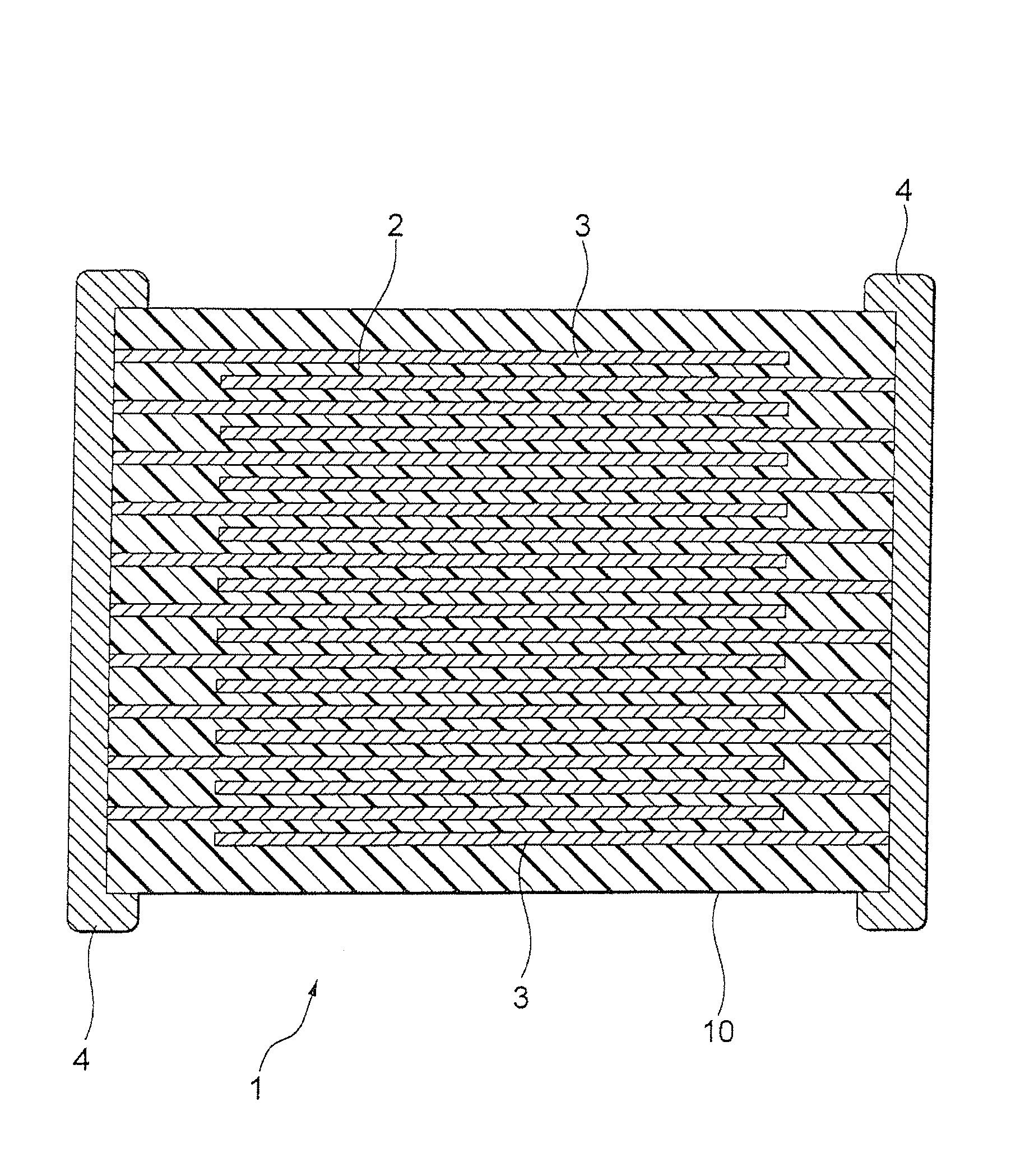
  • Dielectric ceramic composition and electronic device
  • Dielectric ceramic composition and electronic device

Examples


example 1

[0065]At first, a compound powder shown by a general formula {A1−x(RE)2x / 3}y-D2O5+y was prepared. In the general formula, “A” element is Ba, “RE” element is La, “D” element is Nb, “x” is 0.40 and “y” is 1.000.

[0066]Next, as a raw material of “M” oxide, Al2O3 powder, SiO2 powder, B2O3 powder and Li2O powder were prepared.

[0067]And then, each raw material was weighed and mixed so as to make the composition after firing become the composition shown in Table 1, and dielectric raw material was obtained.

[0068]Next, ion-exchange water and polyvinyl alcohol were poured in a container, mixed for 2 hours at 85° C., and then polyvinyl alcohol aqueous solution was obtained. Concentration of the aqueous solution was made to 6 wt % by regulating an amount of ion-exchange water.

[0069]20 wt % of polyvinyl alcohol aqueous solution with respect to 100 wt % of the prepared dielectric raw materials was added, mixed and granulated in a mortar, and then granulated powder was obtained. The obtained granul...

example 2

[0083]Samples of ceramic capacitor were manufactured in the same way as sample 4 of Example 1, except using a mixture of a powder of the compound used in example 1, an oxide powder of “M” and an oxide powder of Mg, and regulating the mixture so that the composition after firing show the composition shown in Table 2. And then contraction ratio, specific permittivity and further, the following “excessive particle growth” were evaluated. Results are shown in Table 2.

(Evaluation of “Excessive Particle Growth”)

[0084]First, a range of 5×5 mm on the surface of green compact before firing was observed by metallograph; and then presence and absence of particles having an area of 0.01 mm2 or more were evaluated. Next, a range of 5×5 mm on the surface of dielectric ceramic composition after firing was observed by metallograph; and then presence and absence of particles having an area of 0.01 mm2 or more were evaluated. Then, when particles having an area of 0.01 mm2 or more were not observed b...

example 3

[0087]Samples of ceramic capacitor were manufactured in the same way as sample 4 of Example 1, except using a mixture of a powder of the compound used in example 1, an oxide powder of Si, an oxide powder of Mg, an oxide powder of Ti and an oxide powder of Zr and regulating the mixture so that the composition after firing show the composition shown in Table 3. And then evaluations in the same way as Example 2 were performed. Results are shown in Table 3.

[0088]

TABLE 3Characteristics of a sintered bodyOxideFiringContractionExcessive(Ba1−xLa2x / 3)yNb2O5+yAlSiTiZrMgTemperatureSpecificRatioParticle Samplesxy[mol][mol][mol][mol][mol][° C.]Permittivity[%]Growth40.401.000—1.0———130042017.4existence400.401.000—1.0———126039016.6existence410.401.000—1.01.0——126040717.2existence420.401.000—1.0—1.0—128042217.2existence430.401.000—1.01.0—1.0126039917.4non-existence440.401.000—1.0—1.01.0128041317.4non-existenceContents of oxides are shown in terms of element, with respect to 100 moles of (Ba1−xLa2x / ...


PUM

PropertyMeasurementUnit
holding temperatureaaaaaaaaaa

Abstract

A dielectric ceramic composition comprising a compound shown by a general formula {A1−x(RE)2x / 3}y-D2O5+y having tungsten bronze-type structure and an oxide of “M”. “A” is at least one selected from Ba, Ca, Sr and Mg, “D” is at least one selected from Nb and Ta, “RE” is at least one selected from Sc, Y, La, Ce, Pr, Nd, Sm, Eu, Gd, Tb, Dy, Ho, Er, Tm, Yb and Lu, “x” and “y” satisfies 0<x<1 and y>0, respectively and said “M” is at least one selected from Al, Si, B and Li. It is preferable to further comprise Mg oxide.

Description

CROSS-REFERENCE TO RELATED APPLICATION[0001]This application is based upon and claims the benefit of priority of the prior Japanese Patent Application No. 2012-044017, filed Feb. 29, 2012, the disclosure of the prior application is hereby incorporated in its entirety by reference.BACKGROUND OF THE INVENTION[0002]1. Field of the Invention[0003]The present invention relates to a dielectric ceramic composition and electronic device wherein said dielectric ceramic composition is applied to its dielectric layer. More precisely, the present invention relates to a dielectric ceramic composition having good characteristics under a high electric field intensity, and to an electronic device, wherein said dielectric ceramic composition is applied to dielectric layer, having an electrode.[0004]2. Description of the Related Art[0005]In recent years, a demand for a high reliability of electronic device is high. For instance, size reduction and high performance of multilayer ceramic capacitor, an ...

Claims


Application Information

Patent Timeline
Patent Type & Authority Patents(United States)
IPC IPC(8): C04B35/495C04B35/50H01G4/10C01G33/00C04B35/626H01G4/12H01G4/30
CPCC04B35/50C04B35/6263C04B35/495H01G4/1254H01G4/1209H01G4/30C01G33/006C04B2235/3215C04B2235/3239C04B2235/3409C04B2235/3418C04B2235/3272C04B2235/3256C04B2235/9615C04B2235/3258C04B2235/6562C04B2235/3208C04B2235/3229C04B2235/3251C04B2235/3227C04B2235/3217C04B2235/656C04B2235/3225C04B2235/3224C04B2235/3203C04B2235/76C04B2235/3262C04B2235/3206C04B2235/3213C04B2235/3241C04B2235/78
Inventor IGUCHI, TOSHIHIROYOSHII, AKITOSHIKOJIMA, TATSUYATAKAGI, SATOSHI
Owner TDK CORPARATION
Learn More