
Wireless motor control system

a control system and wireless technology, applied in the direction of vehicle position/course/altitude control, process and machine control, instruments, etc., can solve the problems of unwanted interference, limited control range, limited industrial digital channel bandwidth, etc., and achieve the effect of preventing interference with other wireless devices

Inactive Publication Date: 2014-10-07
YEH CHIEN HONG
View PDF5 Cites 5 Cited by
  • Summary
  • Abstract
  • Description
  • Claims
  • Application Information

AI Technical Summary

Benefits of technology

The present invention is a wireless remote control system that uses a unique digital identity and the IEEE 802.15.4 Zigbee transmission method. This system prevents interference with other wireless devices and can effectively control the current of a motor. The connection device is designed to bear a very large current and can prevent damage to the motor or devices driven by it in case of a current surge. The technical effects of the invention are improved remote control and efficient control of motor current.

Problems solved by technology

In general, a radio frequency signal is used as the form of transmission, however, the bandwidth of the industrial digital channel is limited that signals from the transmitters may be transmitted to other devices or equipments such as winches or other hardware with the similar frequencies can cause unwanted interferences.
Not only the control range is limited to a short distance, but also the accuracy is relatively low, which may cause accidents or danger to users.
In addition, the aforementioned devices including the portable hoist, truck tarp cover or winch that the motor may produce over-current and causes damages to the device.
It is an important and urgent issue to protect the motor from over-current.

Method used


Image

  • Wireless motor control system
  • Wireless motor control system
  • Wireless motor control system

Examples


Embodiment Construction

[0018]The technical contents of the present invention will become apparent with the detailed description of preferred embodiments and the illustration of related drawings as follows.

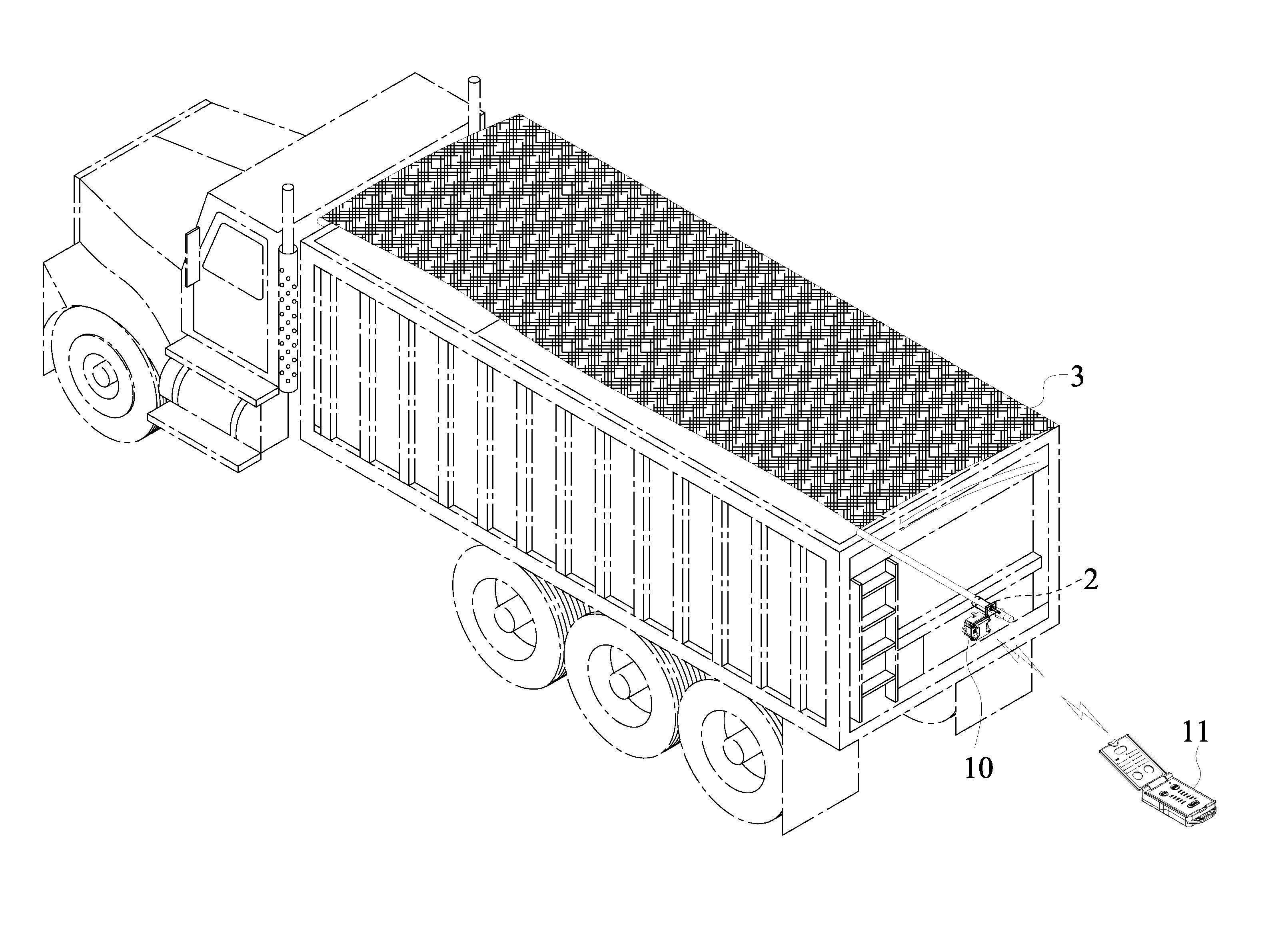
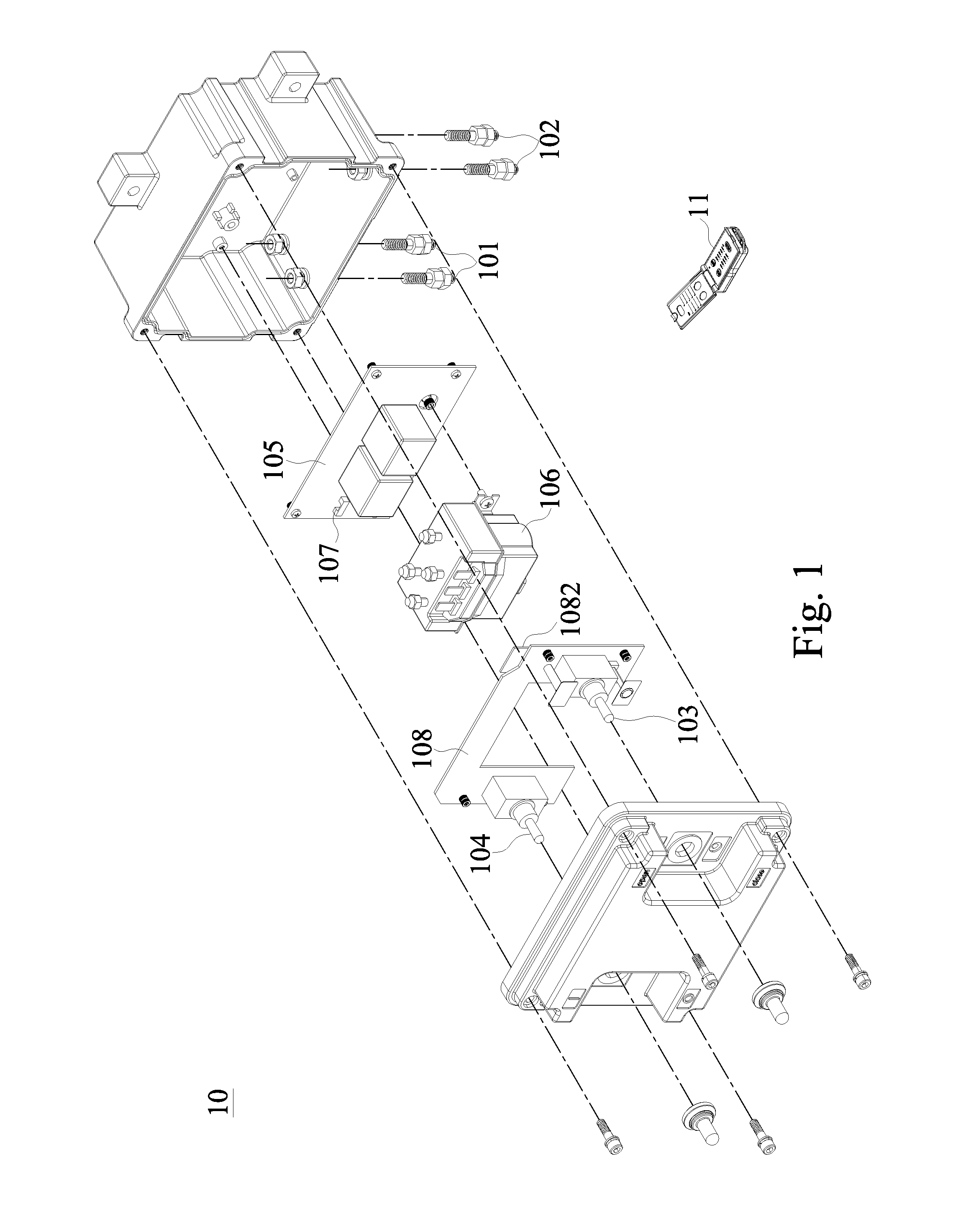
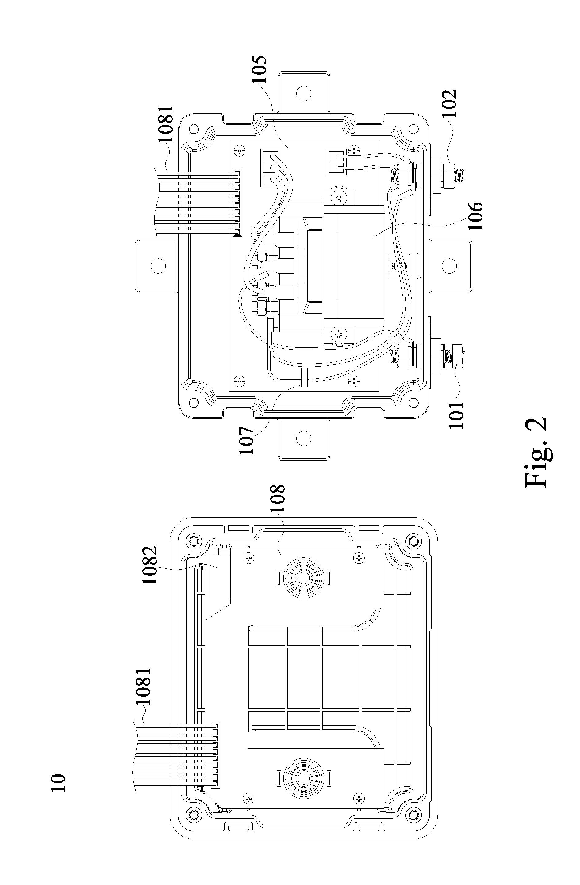
[0019]With reference to FIGS. 1 to 5 for an exploded view of a connection device, a schematic circuit diagram of the connection device, an exploded view of a remote control device, a perspective view, and a schematic view of an application in accordance with a preferred embodiment of the present invention respectively, a wireless motor control system 1 of the present invention comprises at least one connection device 10 and a remote control device 11.

[0020]The wireless motor control system 1 is provided for a user to control the operation of a motor 2 through a wireless transmission method complied with the IEEE 802.15.4 Zigbee transmission method, wherein the motor 2 is installed at a machinery equipment such as a portable hoist or a winch, or used for opening or closing a large object such as an electr...


PUM


Abstract

A wireless motor control system includes a connection device and a remote control device. The connection device has a pair of motor connection terminals and a pair of power connection terminals for connecting a motor and an electric power source. The connection device contains a second control circuit board having a processing element, and the processing element has a digital identity for interconnecting the connection device with a control element of the remote control device to form a unique signal transmission channel, and a Zigbee transmission method complied with IEEE 802.15.4 standard forms a group control network. With a relay and a current detector installed in the connection device, the power of the motor is disconnected immediately when there is an over-current.

Description

BACKGROUND OF THE INVENTION[0001]1. Field of the Invention[0002]The present invention relates to the technical field of motor control, and in particular a control system capable of controlling the operation of a motor via a wireless remote control and providing the mechanism to protect the control system and preventing interferences between the wireless systems.[0003]2. Description of the Related Art[0004]To facilitate the control of the devices such as a portable hoist, a truck tarp cover, or a winch and to prevent operators of the devices from being too close to danger, a controller is used to control the operation of the motor from a safe distance through wireless remote control. In general, a radio frequency signal is used as the form of transmission, however, the bandwidth of the industrial digital channel is limited that signals from the transmitters may be transmitted to other devices or equipments such as winches or other hardware with the similar frequencies can cause unwan...

Claims


Application Information

Patent Timeline
Patent Type & Authority Patents(United States)
IPC IPC(8): H04B1/00H02H7/08G05D1/02
CPCH02P3/02G08C17/00G08C17/02
Inventor YEH, CHIEN-HONG
Owner YEH CHIEN HONG
Learn More