
Tight depth range occlusion prediction system and method

a depth range occlusion and depth range technology, applied in the field of graphic processing, can solve the problems of consuming significant power, requiring intensive data processing, and consuming considerable time to process, so as to reduce the rendering work required, improve performance, and improve performance

Active Publication Date: 2014-10-07
NVIDIA CORP
View PDF42 Cites 17 Cited by
  • Summary
  • Abstract
  • Description
  • Claims
  • Application Information

AI Technical Summary

Benefits of technology

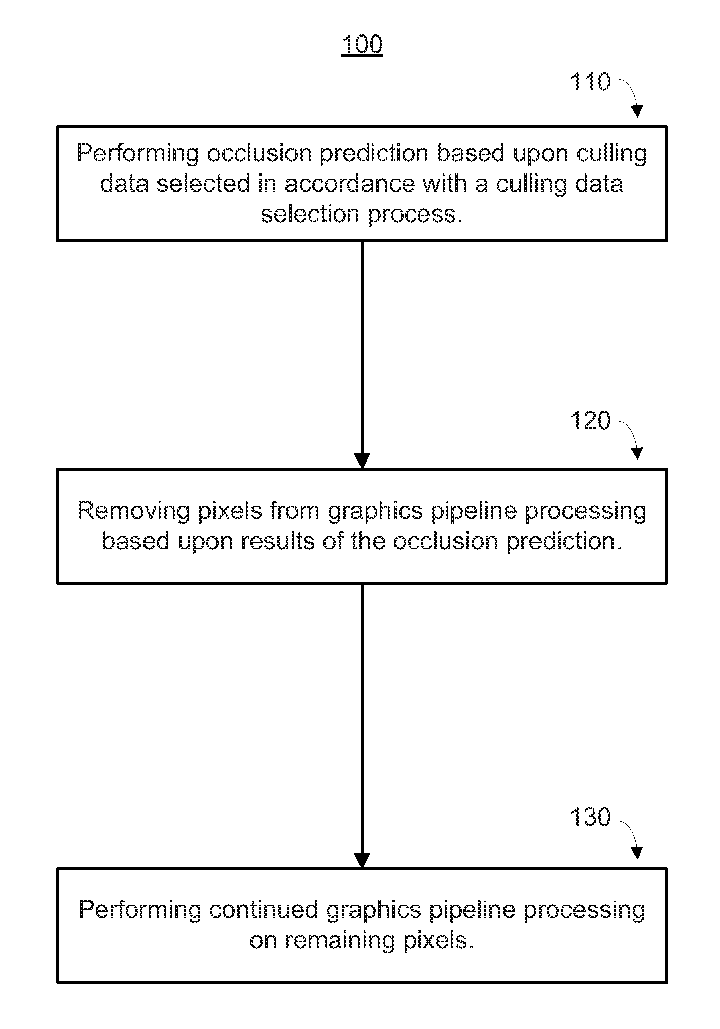
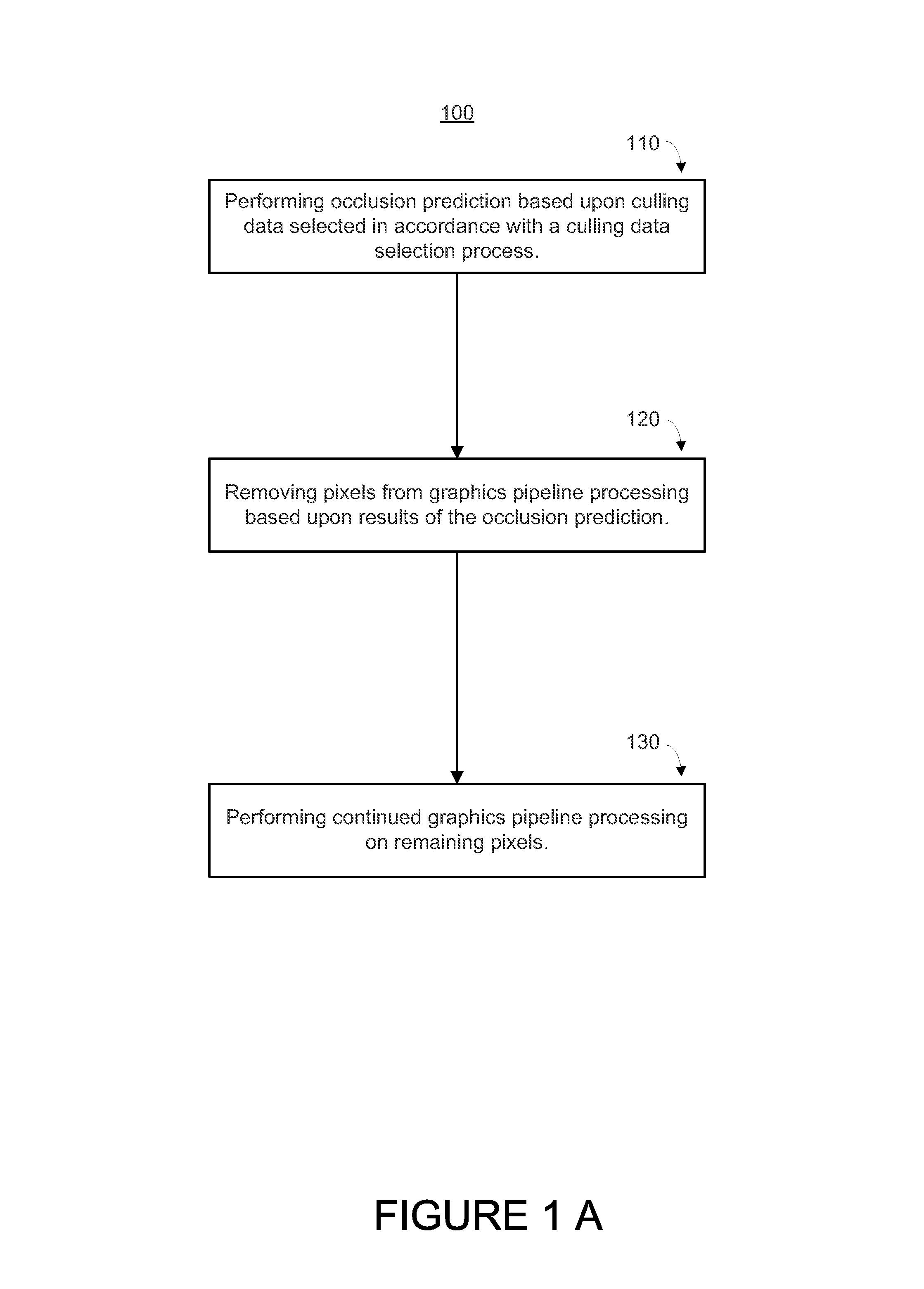
This patent presents a method to predict which parts of a image will be able to be seen without causing confusion or overlapping. By analyzing the depth values of pixels and comparing them to previously-rendered points, the method can determine which parts will be visible and which parts will be hidden. This helps to improve the performance of the image processing system by avoiding unnecessary work and reducing the amount of data that needs to be generated. Additionally, the method can also improve power consumption by only processing the necessary data.

Problems solved by technology

Displaying graphics images usually requires intensive data processing which traditionally takes considerable time to process and often consumes significant power.
Providing information for each pixel is very data intensive and consumes a significant amount of processing resources.
These manipulations often involve numerous computational processes that take a relatively long time to complete.
In addition, the processing consumes significant power and can be a significant drain on limited power supplies, such as a battery.
Slow rendering rates often result in undesirable choppy or “jerky” presentations which usually results in a user experience that is non-immersive and unpleasant.
The rate at which graphics systems can render images is often limited by the rate at which the processing devices can process the graphics information.
However, users tend to have ever increasing demands for ever more spectacular and clearer images with better resolutions.
As more information associated with sophisticated applications and complex image rendering is fed into traditional graphics pipelines, the time required to process all the information increases since the graphics processing capabilities of the graphics systems typically have an upper limit.
In addition, accessing the increased amounts of information also increases the time involved in retrieving the information from various memories.
The increases in time to perform processing and information accesses typically slows the rendering rate and adversely impacts the graphics presentation.

Method used


Image

  • Tight depth range occlusion prediction system and method
  • Tight depth range occlusion prediction system and method
  • Tight depth range occlusion prediction system and method

Examples


Embodiment Construction

[0022]Reference will now be made in detail to the preferred embodiments of the invention, examples of which are illustrated in the accompanying drawings. While the invention will be described in conjunction with the preferred embodiments, it will be understood that they are not intended to limit the invention to these embodiments. On the contrary, the invention is intended to cover alternatives, modifications and equivalents, which may be included within the spirit and scope of the invention as defined by the appended claims. Furthermore, in the following detailed description of the present invention, numerous specific details are set forth in order to provide a thorough understanding of the present invention. However, it will be obvious to one of ordinary skill in the art that the present invention may be practiced without these specific details. In other instances, well known methods, procedures, components, and circuits have not been described in detail as not to unnecessarily ob...


PUM


Abstract

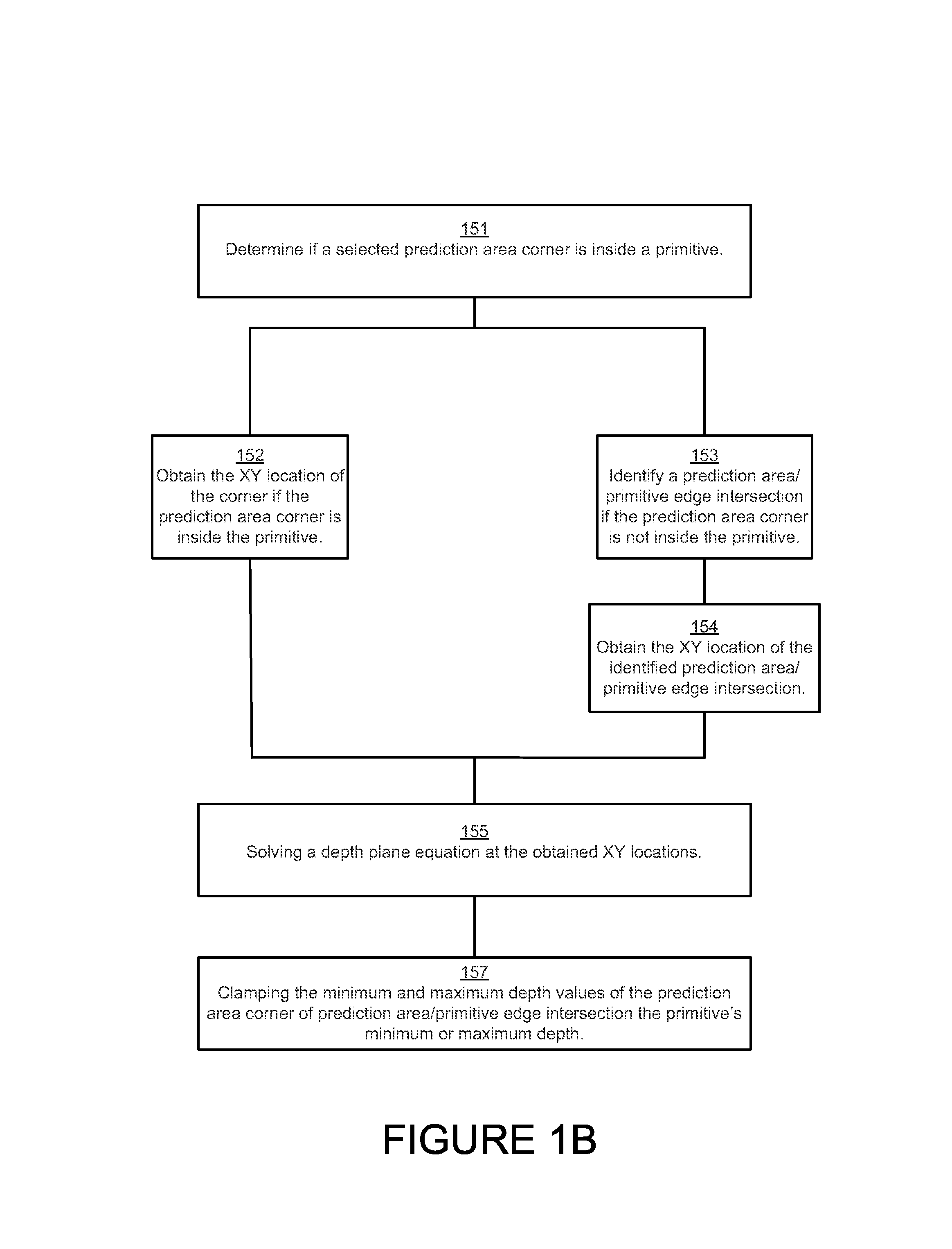
The range of depth values within the overlap of a convex polygon and a square or rectangular rasterization area can be determined by identifying whether the minimum and maximum depth values occur at the corners of the rasterization area or at intersections of the polygon's edges with the area's sides. By choosing between the corner and intersection for both the minimum and maximum depth limit, solving the depth plane equation at the chosen location, and clamping against the polygon's vertex depth range, a tight depth range describing the depth values within that overlap are obtained. That tight depth range is utilized to cull pixel values early in the pipeline, improving performance and power consumption.

Description

RELATED APPLICATIONS[0001]This application is a continuation-in-part and claims the benefit of commonly-owned U.S. patent application Ser. No. 10 / 745,160, filed Dec. 22, 2003, now U.S. Pat. No. 8,390,619 entitled “AN OCCLUSION PREDICTION GRAPHICS PROCESSING SYSTEM AND METHOD” which is hereby incorporated by this reference. This application is a continuation-in-part and claims the benefit of commonly-owned U.S. patent application Ser. No. 10 / 745,277, filed Dec. 22, 2003, now U.S. Pat. No. 8,269,769 entitled “AN OCCLUSION PREDICTION COMPRESSION SYSTEM AND METHOD” which is hereby incorporated by this reference.FIELD OF THE INVENTION[0002]The present invention relates to the field of graphics processing.BACKGROUND OF THE INVENTION[0003]Electronic systems and circuits have made a significant contribution towards the advancement of modern society and are utilized in a number of applications to achieve advantageous results. Numerous electronic technologies such as digital computers, calcul...

Claims


Application Information

Patent Timeline
IPC IPC(8): G06T15/40G06T15/10G06T15/00G09G5/00
CPCG06T15/40
Inventor VOORHIES, DOUGLAS, A.
Owner NVIDIA CORP
Learn More