System and method for robot safety and collision avoidance

a robot safety and collision avoidance technology, applied in the field of robot control, can solve the problems of unanticipated intrusion of robots, large perimeters that have to be established, and consume valuable factory space, so as to avoid undesired collisions, and improve the safety of industrial robots

Inactive Publication Date: 2014-10-07
KAPOOR CHETAN
View PDF19 Cites 24 Cited by
  • Summary
  • Abstract
  • Description
  • Claims
  • Application Information

AI Technical Summary

Benefits of technology

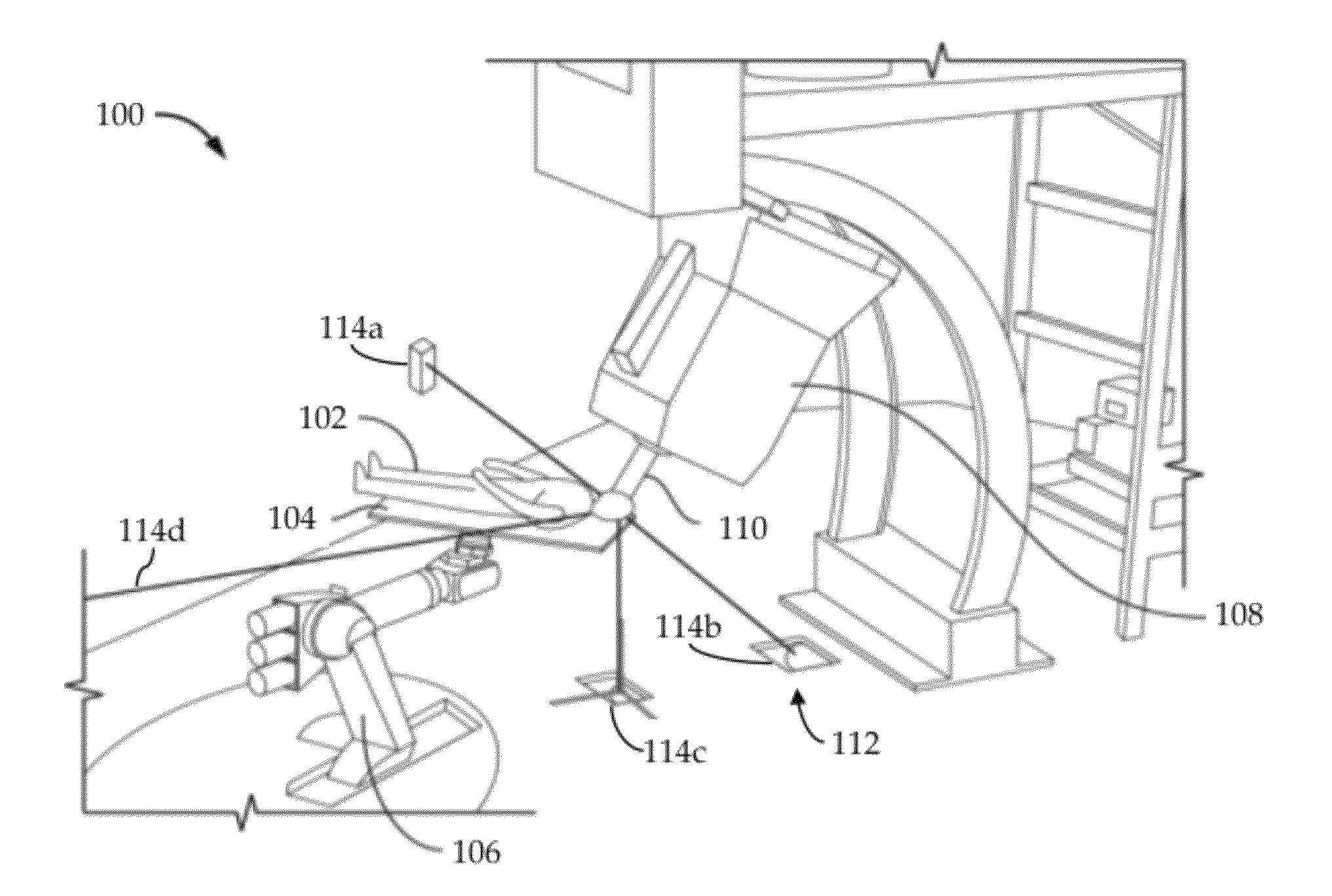
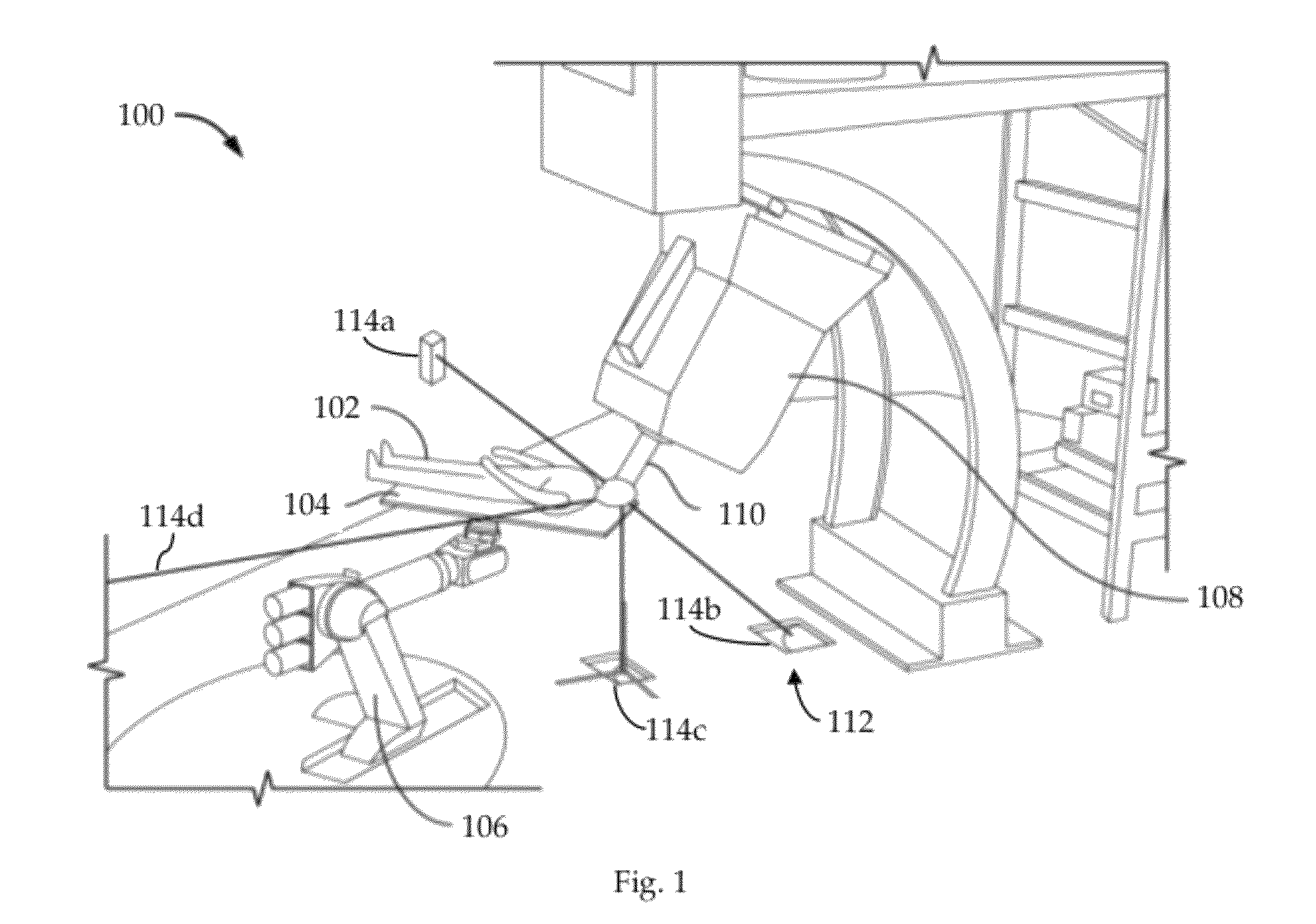
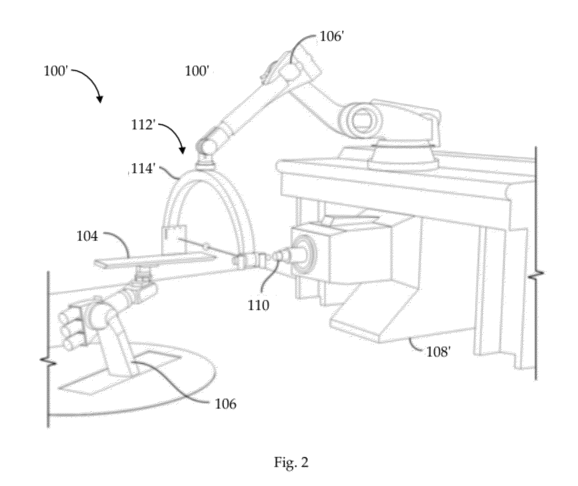
[0015]In accordance with a fifth embodiment of my invention, I provide a method for improved safety of industrial robots by avoiding undesired collisions. The robot is instrumented with a plurality of sensors to create an intrusion zone around movable components of the robot, each sensor adapted to develop a sensor signal during an operation of the robot; and then a model is developed for each robot component to determine expected sensor signals for each sensor at predefined time intervals in the operation of the robot due to intrusions of other robot components. During each time interval of the operation of the robot, sensor signals developed by the sensors are correlated to the respective expected sensor signal; and an exception is signaled in response to any non-correlation.
[0016]I submit that this invention provides a system and method for improved robot safety and collision avoidance which allows for accepted contact between robot components and specific, identifiable objects in the environment of the robot.

Problems solved by technology

Furthermore, it is of no relevance in such systems which specific voltage levels are selected to represent each of the logic states.
Unfortunately, once installed and operating within its workcell, the robot may be exposed to unanticipated intrusions.
One drawback of such systems is that the size of the perimeter has to be established given the worst case scenario of the robot operation.
As a result, these perimeters tend to consume valuable factory space.
One limitation of this approach is that it only detects intrusion into the workspace of the robot and does not necessarily identify any inadvertent changes that may have taken place inside the workspace, e.g., accidental movement of a workspace fixture.
Also, this technique still uses gross models, and thus is limited only to perimeter guarding.
To date, however, such techniques have not been successfully extended to articulated robot manipulators, as they require a 3D world model, which is significantly harder to develop in 3D space.
However, a complete world model cannot be guaranteed as, usually, at least some significant portion of the robot and its workspace may be occluded to the vision components.

Method used


Image

  • System and method for robot safety and collision avoidance
  • System and method for robot safety and collision avoidance
  • System and method for robot safety and collision avoidance

Examples


case 1

[0048] A rectangular link with all angles between different faces of the link being 90° as shown in FIG. 9a. For the top face of the link, first fit a square to the FOV of the sensor (located at the center as indicated by the small circle) at the appropriate depth, d, as shown in FIG. 9b; each side of the square will, therefore, be of size w, where w=sqrt(2)*d*tan(θ / 2). For sensor placement purposes, I will assume that each sensor will detect an intrusion at distance d and w×w area. Assuming the length of the face of the illustrated robot link is lr and width is wr the maximum distance between any two sensors can be d. This will provide full coverage of the given face of the robot link as shown in FIG. 9c. Assuming that n1 is the number of sensors placed along the length of the robot link, then:

nl>lr / (2*w).

Similarly, if nw is the number of sensors placed along the width of the robot link, then:

nw>wr / (2*w).

The same method of sensor placement, when applied to each face of the rectangu...

case 2

[0049] A rectangular link where the angle between any two faces may not be 90° as shown in FIG. 9d. FIG. 9e illustrates a side view of one surface of this link having an angle, Sangle , greater than 90° between two adjacent, contiguous faces. As Sangle decreases, e.g., as a result of a joint rotation, any two sensors that are mounted at the edge interface between the two faces will tend to move away from each other, requiring that additional sensors (indicated by arrows as shown in FIG. 9f) be placed along the joint to maintain full coverage.

[0050]With reference to the illustration of FIG. 9g, the number of edge sensors that will be required to get full coverage can be computed as:

No. of Edge Sensors>=(180−ø−Sangle) / ø

[0051]where: ø=2*arctan(tan(θ / 2) / sqrt(2))

case 3

[0052] Cylindrical link. In the case of a cylindrical link, the placement along the length of the cylinder will be similar to that along the length of a face of a rectangular link; the placement along the circumference of the cylinder requires a different formulation. Shown in FIG. 9h is the cross section of a cylinder of radius r with a representative placement of proximity sensors around it. In general, the proximity sensors are placed regularly around the circumference of the cylinder at an angle, α, with respect to each other. The value of α that would provide full coverage of this cross-section of the cylindrical link can be computed as:

α=2*arctan((d*tan(θ / 2)) / (d+r)).


PUM


Abstract

A system and method for developing an intrusion detection zone substantially surrounding mobile components of a robot, training a model of the robot to accept selected intrusions into the intrusion detection zone, and, during application operations, triggering an application interrupt upon detecting an unexpected intrusion.

Description

CROSS-REFERENCE TO RELATED APPLICATIONS[0001]This application claims priority to the U.S. Provisional Patent Application Ser. No. 61 / 367,009 (“Parent Provisional”), filed 23 Jul. 2010. The subject matter of this application is related to U.S. application Ser. No. 12 / 910,124 (“Related Application”), filed 22 Oct. 2010. (Collectively, “Related References”). The subject matter of the Related References, each in its entirety, is expressly incorporated herein by reference.BACKGROUND OF THE INVENTION[0002]1. Field of the Invention[0003]The present invention relates generally to control of robots, for example, but not limited to industrial, medical, and defense robots, and more particularly to robot safety and collision avoidance.[0004]2. Description of the Related Art[0005]In general, in the descriptions that follow, I will italicize the first occurrence of each special term of art which should be familiar to those skilled in the art of robot control systems. In addition, when I first int...

Claims


Application Information

Patent Timeline
Patent Type & Authority Patents(United States)
IPC IPC(8): G06F19/00
CPCB25J9/1666Y10T307/826
Inventor KAPOOR, CHETAN
Owner KAPOOR CHETAN
Why Eureka
Try Eureka